+12V on the CANH and CANL of the CAN bus battery

Mitsubishi i-MiEV Forum

Help Support Mitsubishi i-MiEV Forum:

This site may earn a commission from merchant affiliate links, including eBay, Amazon, and others.

avilinks

Member
Joined
Jun 30, 2020
Messages
13
Location
France
Hello everyone,

I started developing a residential battery to store solar electricity.

My project is well advanced, I managed to connect a homemade card to the battery, read the CAN frames sent by the CMU cards and control a Solax inverter to manage the charging/discharging of the battery.

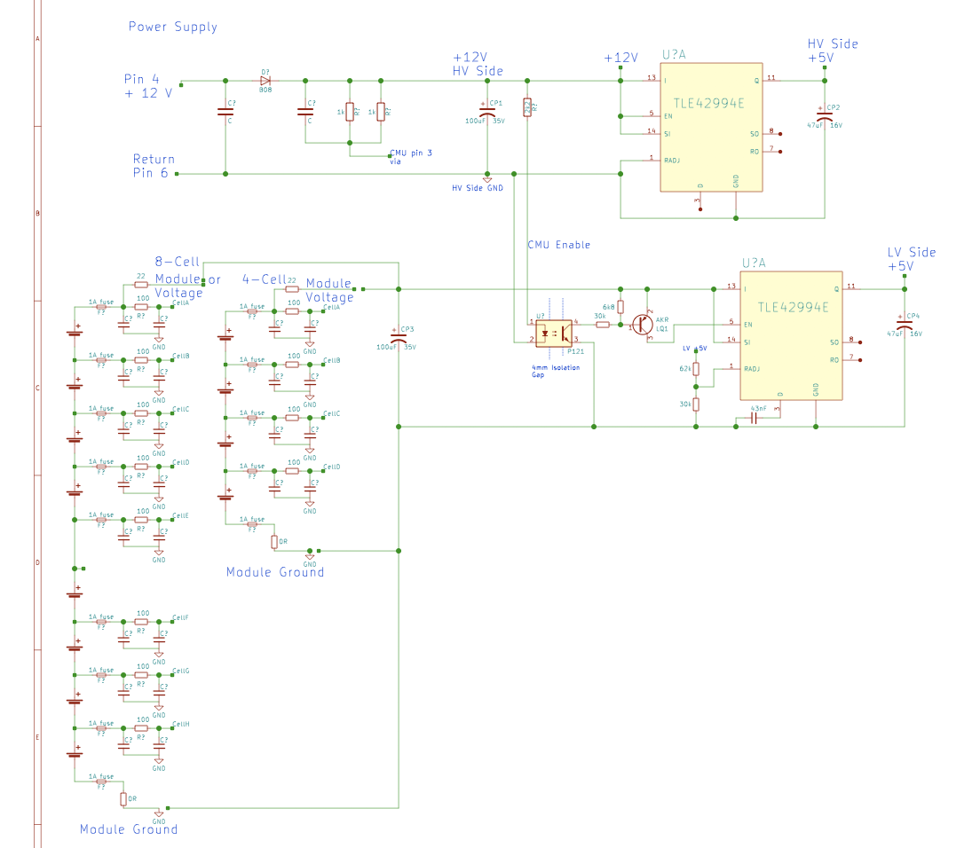
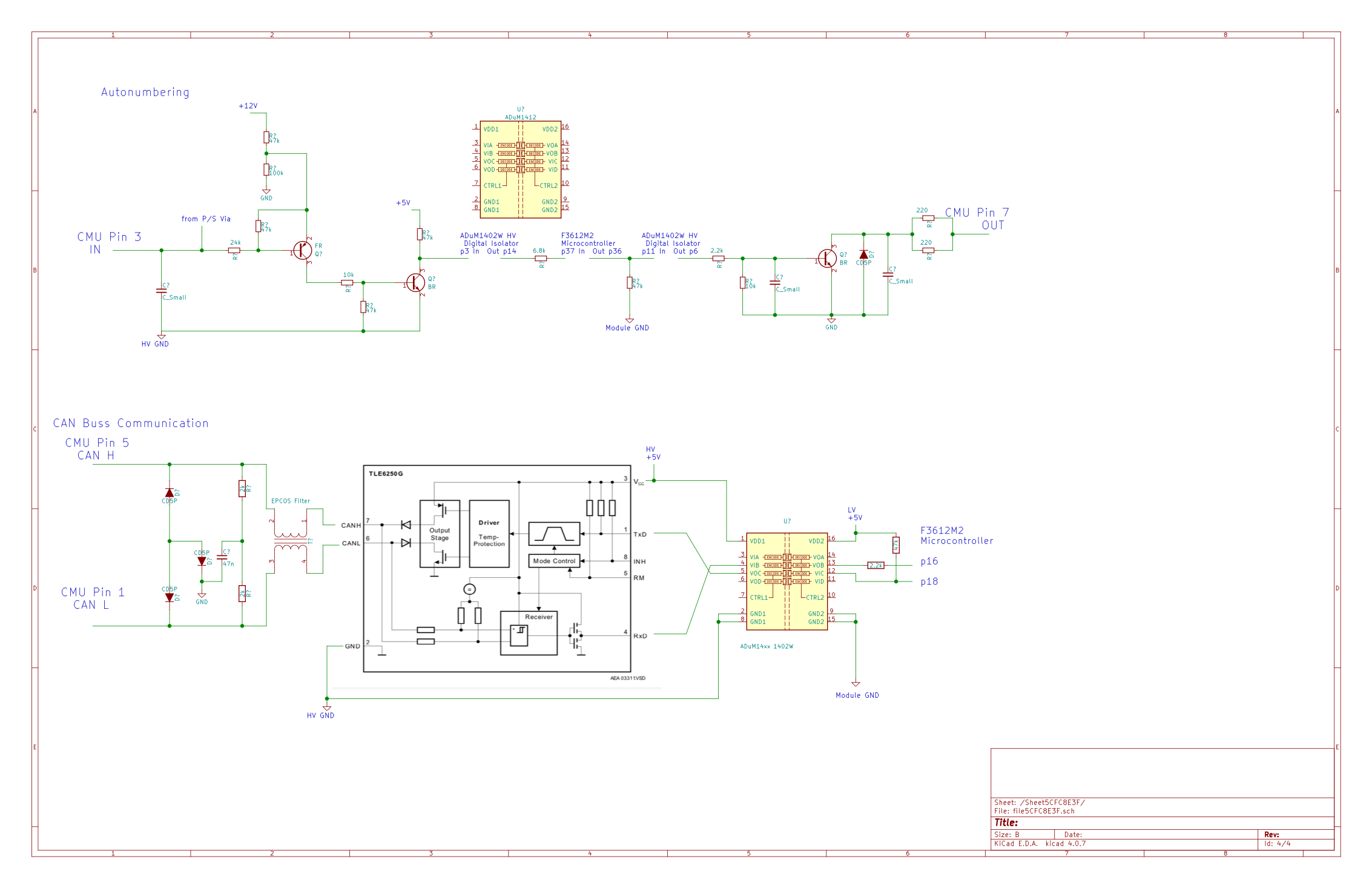
Today, the battery's CAN bus no longer works at all. A voltage of 12V appears on the two signals CANH and CANL as soon as I supply the battery with 12V.

Several people on the forum have looked very closely at the CMU cards.

Do you have any idea what could be happening?

I'm very afraid of having made a mistake on the CAN bus and having broken all the CMU cards...

I thank you very much in advance for the help and the ideas that you are willing to share.

Have a nice day

Dom
 
Howdy Dom, and welcome to the forum,

Sounds like you have an interesting project--hope you can share some with us after the issue is resolved.

How long has your project been in operation? How long was the 12V disconnected before this last connection incident occurred?

Possibly related thread:
https://myimiev.com/forum/viewtopic.php?p=45544#p45544

CMU board thread:
https://myimiev.com/forum/viewtopic.php?p=39002#p39002

Power supply schematic:
U5UoqjH.png


The power supply section schematic shows there are 5V low voltage supplies on both sides of a 4mm High Voltage isolation gap--one is isolated toward the 4 or 8 cells of that particular module and is called the "LV" supply and ground; the other is exposed toward the rest of the pack and called the "HV" supply and ground. These are merely names that i created to reference the supplies based upon their location.


The cell autonumbering wires and CAN are on this schematic:
qiG1Mk0.png


i don't see any connection to a 12V voltage on the CAN buss from the module side so i suspect it might be on the interface board that you built and are using. If you want to post up a schematic then the guys here would take a look and give you some helpful advice.
 
Thanks a lot for your answer.
It seems that I let my battery discharge too long, it is completely empty and certainly dead: I measure 55V across its terminals.
CMU cards may refuse to operate when the cells are over discharged.
It's a shame, my project was almost finished.

My project was to connect a CZero battery to an inverter without opening the battery.

I had developed a small esp32 base card. This card recovered the voltages from the battery cells on the CAN bus, controlled the battery relays as well as the ventilation. This card was also connected to the CAN bus of my Solax hybrid X1 G4 inverter and simulated the presence of a Solax battery.

Everything was working well, except the balancing which I did not have time to develop (in the meantime, I stay below the min/max voltages of the cells)

To prevent the battery from setting the house on fire if something went wrong, I was digging a hole behind my house to bury the battery. This solution had the advantage of keeping the battery cool, as heat seemed to be the biggest enemy of our batteries.
Family constraints prevented me from finishing the hole behind the house this summer. So, I had to leave the battery disconnected for 4 months. I didn't think the battery could drain so quickly.

Finding another battery is mission impossible, I will have to put an end to my project.

If anyone is interested in this project, I will be happy to share my knowledge and what I have developed.
 
If you don't try to charge too quickly, then you may find that the cells could be recharged. You would need an adjustable power supply with current limiting if you decided to test this out. The biggest factor is the rate of discharge that was experienced by the cells, whether slow or fast.

There is a "bounce" test that is done on fully discharged cells to determine if they are viable, basically if the voltage comes back up after being drained to 0.0 volts. Since your pack is not at 0.0 volts then it would seem to still have some active cells.

No need to pull it down lower. i would try to charge it up to 80 or 88 volts (1 Vpc) at 1 Amp or less, and then see if it holds or drops from that level. If it holds then good news, but if it drops quickly then not so much good.

If you decide to open the pack then modules and cells could be evaluated separately and some of it might be saved.
 
Wow Dom, sorry to hear that! I have sEVeral i-MiEV packs ready for stationary storage projects, but I'm guessing that you're in Europe.
I'd enjoy continuing your project. Solax does not have much of a market presence in the USA, but their one dealer in the Western US, Emporia is a reputable company. Please PM contact details to continue discussion.
 
Thank you Kiev for your advice thanks to which I am perhaps resuscitating my battery.

The cells that I recharge at 250mA now have a voltage of 3.2V!
 
Yes, news are still good, I charged 3 packs until 3,7V per cell. My power supply is to low, but I will order a 400V power supply to allow me to keep all the pack charged (and it will be more convenient when I develop the balancing source code)

I disconnected all the packs from the CAN bus inside the battery box and connected only one charged pack, powered the 12V to the battery and I have CAN messages !
 
Back
Top