The Troubleshooting and Repair for On-board Charger (OBC) Thread

Mitsubishi i-MiEV Forum

Help Support Mitsubishi i-MiEV Forum:

This site may earn a commission from merchant affiliate links, including eBay, Amazon, and others.
oh yes the picture shows now.

They are brittle ceramic capacitors and clearly have cracked--maybe they got smacked by a tool or something dropped?

The black potting has been removed from around the large can caps?
 
Yes I got the board used and supposedly repaired, apparently someone had replaced the big cans with even larger ones (but same values), changed the 2.2myF capacitor in the AC pinput and snubber caps. As everything is soldered through the holes I suppose the Wafflelate™ had been removed as well
 
Ok, I replaced capacitors C112 & C113 with round ceramic ones, each 1nF.

Now the car is charging :shock: :D !!!

Thanks for your immediate help Kenny, just brilliant! Yippee!

view


Cheers, Joerg
 
Oh, by the way: although everything is working as it should now I still have DTCs

Dashboard/Meter #2: U1116 - invalid or missing data for electrical energy management, KOS CAN timeout / Not equipped
BCM/ETACS #2: U1111 - invalid or missing data for primary ID Display CAN timeout / Not equipped
E/V ECU: U1113 - invalid or missing data for primary ID Display CAN timeout / Not equipped

They seem unrelated or even normal for the European version (Citroen C-Zero). As it says „not equipped“ I suppose something is missing in the rebranded version of the iMiEV.
 
We are still trying to repair Waffleplates, so someone who works at an automotive research institute here in Germany had another x-ray taken at the IFAM (Frauenhofer Institute for Manufacturing Technology and advanced Materials) which I’d like to share:

view


We were so far successful in milling down a defective IGBT to its wire connectors, ready to solder a new one to them. We just don’t know yet which exact make and type to get. Is there a final consent about this? Further up someone found an IR part number GS30B60K on one of the IGBTs, but I recall that was from a different Waffle Plate (earlier version OBC, I think from 2010). But I think it should work with the newer model OBC as well.
 
That's excellent! Seems like i looked up the FETs used in the 2nd Gen units and found there was a similar package available as used in the Gen1, so that was going to be my choice.

[edit] i think they are the D-Pak version of the Gen 2 OBC FETs, STB27NM60ND,
Automotive-grade N-channel 600 V, 0.13 Ω, 21 A FDmeshTM II Power MOSFETs (with fast diode) in D2PAK and TO-247 packages
https://www.mouser.com/datasheet/2/389/stb27nm60nd-955511.pdf

When i have tried to mill or cut into the epoxy, the heat draws carbon out of my cutter bits and dulls them immediately.

IFAM waffle plate Röntgen image with blown FET in lower right quadrant (H-bridge section)
TnLK2cM.png
 
Hello dear forum members! I beg you to help me! My I-miev 2011 won't charge the 12v battery. The main battery is charging normally. I've read the entire forum (it's great!), but so far I haven't been able to solve my problem. I removed the obc, carefully examined all the boards including the lower dc-dc, all contacts, relays, fuses, but the battery is still not charging. There is a 12.6v battery power on the thick white wire included in the dc-dc. I bought a new 12v battery but that didn't help. Autocom diagnostic shows one error P0A09, please tell me what else can I check? Thank you. Capacitors in "dog house smd. OBC 2017.
 
Thanks for the answer! Today I will try to check all the items on the service bulletin. And the block apparently was once replaced, it has the date 2017 on it.
 
Well, you guys have sucked me in. :D

I wrote a couple weeks ago about my failed OBC (in this thread: https://myimiev.com/forum/viewtopic.php?t=5218), basically asking if there was a simple fix or if I needed to scrap the car. Learned of this thread, bit the bullet and read the whole thing. Which was hard, because I know just enough about electronics to be dangerous. My problem is on the AC input side. The car still drives and charges the 12V battery, so the DC/DC is fine and the 20 amp fuse in the MCU is good.

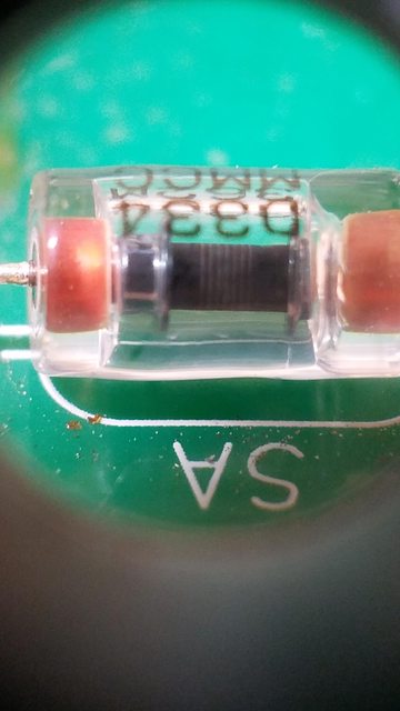
I have my OBC boards out of the car. C106 (2.2 µF) has oozed gray goo all over R106, the non-fused 4.7 Ω ceramic resistor. As near as I can tell, R106 is still good. It measures 5.1 Ω. But R105, the other ceramic resistor with an internal fuse is open circuit. (At least I think so, because sticking wires deep under the waffle plate to get at those leads is tricky.) N on the waffle plate to the neutral Faston is open circuit. Snubber caps are intact, but have a slight brownish hue. The glass-tube component marked "SA" (spark arrestor?) is open circuit both directions, but I don't know what it is, let alone how to test it. Any suggestions? I also found some contacts on the flex circuit to be bent. (Which I might have done inadvertently, or is inconsequential since I understand some of those lines are redundant.)

eAH7O2um.jpg


My approach to this is to look at the potential show-stoppers first.

1) I've checked the diode drops in the waffle plate. They look good, except for the same issue as @adam on page 101. Between points 12 and 13 I got the expected .6 V in one direction, but 1.6 V in the other, and significantly lower resistance values in the lower right quadrant. (16k vs. 90k and 200 vs.1k.) Never saw an explanation for that. Is it OK?

2) I'd prefer to do this once. Since if successful this repair will save me 1000s of dollars, it makes sense to me to just buy a desoldering station to remove the waffle plate to make the rework easier and more reliable. I've never used one, but I have used a hand-held spring plunger type. Is this something a noob can master quickly? It will likely be used only for this repair and then sold (perhaps to the next person with a dead i-MiEV OBC?). Any recommendations? Just go by the reviews at online retailers?

3) If in fact my fused 4.7 Ω resistor is toast, what then? None of the rectangular resistors I've found will fit between the boards, and I'm not a fan of some of the apparently effective but hillbilly-looking hacks some have been forced into. I did find this at digikey: https://www.digikey.com/en/products...loric-bc-components/AC07000004708JAC00/595613 . Is it a good replacement for the non-fused R106? What about the fused one, R105? Is there an inline thermal fuse I could put in series with an axial resistor? If there is such a thing I can't make enough sense out of the P10K data sheet to know how to spec one. How necessary is that fuse, seeing as how the resistors themselves seem to fill that role pretty well?

4) Even if all goes well it gives me pause that several people have replaced the ceramic resistors and tested the relay, but still keep blowing resistors after a repair. Sure seems to me that something is happening upstream of the relay and resistors. I hadn't seen anything discussed about that (other than checking continuity across the flex and its connectors), except that @siggs found a faulty connection to the relay: https://myimiev.com/forum/viewtopic.php?p=45806#p45806 . He also referenced another person doing i-MiEV charger repairs who had found the same problem repeatedly. A bad solder joint doesn't seem like a repeatable problem. Maybe a bad run of relays and the problem is internal? I found this with a 105 °C limit. Is that really high enough, as stinkin' hot as this charger gets? https://www.digikey.com/en/products/detail/cit-relay-and-switch/J114FL1CS165VDC-41/14002174

5) One last thing (for now). I think I remember seeing a photo of an oozed capacitor in the doghouse on top of the OBC lid. I took the metal cover off mine and found a plastic cover underneath. The plastic cover is on there pretty solid, enough that getting it off will likely result in broken plastic. Is there a trick I'm not seeing?
 
ctromley said:
I also found some contacts on the flex circuit to be bent. (Which I might have done inadvertently, or is inconsequential since I understand some of those lines are redundant.)
That flex circuit is really delicate. Unfortunately, it carries the relay coil current from the top board. So if that one thin trace of 0.5 mm copper goes open circuit or intermittent, then this sort of failure is likely.

I like to check the continuity between the top and bottom boards for the relay coil; these are the vias I use:

file.php


You should see the resistance between neutrals go from about 9.4Ω to nearly zero:

file.php


From this AEVA page.

2) I'd prefer to do this once. Since if successful this repair will save me 1000s of dollars, it makes sense to me to just buy a desoldering station to remove the waffle plate to make the rework easier and more reliable. I've never used one, but I have used a hand-held spring plunger type. Is this something a noob can master quickly? It will likely be used only for this repair and then sold (perhaps to the next person with a dead i-MiEV OBC?). Any recommendations?
The Atten units are fairly decent quality, reasonably priced, and available online. A colleague has one, and I use it a fair bit. I've done one Waffle Plate™ removal with it; it went well. There isn't much skill to it, just learn to wiggle the nozzle while the suction is on for a second or so to really suck the solder out before removing the tip.

3) If in fact my fused 4.7 Ω resistor is toast, what then?
It's a significant hassle; those OEM resistors are very compact, have impressive ratings, and are made of solid unobtainium. I've actually been replacing some with a pair of 10Ω ceramic composition resistors in parallel; these have excellent pulse power ratings. So much so, I can use just two 1 W resistors in parallel to replace one 5 W or 7 W resistor. I used a 20 A thermal fuse I had in stock from some other project; I can't seem to find proper pulse ratings for these, so I hope that they last. I wasn't able to find replacements for these either.

The resistors I used were Ohmite OX100KE; Mouser have this value at much less than Digi-Key for reasons beyond my capacity. Some of these can be hard to obtain too. There is a 2 W version as well.

None of the rectangular resistors I've found will fit between the boards, and I'm not a fan of some of the apparently effective but hillbilly-looking hacks some have been forced into.
I resemble that statement! ;) Sometimes you just have to do what you can with the parts that are available.

I did find this at digikey: https://www.digikey.com/en/products...loric-bc-components/AC07000004708JAC00/595613 . Is it a good replacement for the non-fused R106?
That's an interesting find. Unfortunately, I calculate the pulse energy that these resistors have to withstand at about 29 J, and it looks like the 4.7Ω 7 W resistor you found withstands about 6 Ws/Ω, so that's about 28 J. Way too close for my comfort. The 10 W version can handle about 70 J (I didn't write it down, sigh). But it's a monster, at 44 mm long.

What about the fused one, R105? Is there an inline thermal fuse I could put in series with an axial resistor? If there is such a thing I can't make enough sense out of the P10K data sheet to know how to spec one. How necessary is that fuse, seeing as how the resistors themselves seem to fill that role pretty well?
I think that the issue is that the resistors might take a while to open circuit, and with some 3 kW of power dissipated, it could cause a lot of damage and/or fire before they finally let go. Though with that massive overload, you'd think that they'd blow pretty quickly. But you have to balance the slight extra safety against the hassle of finding a suitable fuse, and the unreliability that you might build in by installing one that can't take the pulse current for very many starts.

4) ... I found this with a 105 °C limit. Is that really high enough, as stinkin' hot as this charger gets? https://www.digikey.com/en/products/detail/cit-relay-and-switch/J114FL1CS165VDC-41/14002174
I used FTR-K1AK005T, which seems to be the replacement for the originals.

5) One last thing (for now). I think I remember seeing a photo of an oozed capacitor in the doghouse on top of the OBC lid.
It seems quite common for some reason. Maybe it's the cause of some failures, perhaps intermittently shorting (which they are designed not to do, but then they should not be oozing innards either). So I think it's worth checking. I've not come across a model with the external mains filter as yet, so I can't help with the plastic cover.
 
Thanks for the photo of the vias for the relay coil check. (I am not looking forward to trying to continuity check on those fine-pitch solder pads.)

coulomb said:
I've actually been replacing some [4.7 Ω ceramic resistors] with a pair of 10Ω ceramic composition resistors in parallel; these have excellent pulse power ratings. So much so, I can use just two 1 W resistors in parallel to replace one 5 W or 7 W resistor. I used a 20 A thermal fuse I had in stock from some other project; I can't seem to find proper pulse ratings for these, so I hope that they last. I wasn't able to find replacements for these either.

So as hard a life as these things get, would it be an advantage to use the 2W version if I can physically fit them in? If for no other reason than thermal mass?

As for the fuse, does this look good? https://www.tme.com/us/en-us/details/bf157x/thermal-fuses/aupo/ (I initially found this on eBay, https://www.ebay.com/itm/1715113062...efaultOrganicWeb&_trksid=p2047675.c101224.m-1, but thought I'd poke around for a more trustworthy source. The China-based eBay seller has much lower shipping cost and a longer ship time.) This is a 157 °C version that matches the original. Assuming it's a good candidate, would it be best to silicone bond it to the parallel resistor pair that stands in for the P10K component, R105, for good thermal contact?
 
Hello! As I already wrote, my problem is that the small 12v battery is not charging. In this case, a large battery is charged normally. Code P0A09 is present. The 12v battery has been replaced with a new one. The car was checked against a Mitsubishi bulletin for P0A09 and diagnostics showed a faulty OBC. I had the opportunity to borrow the OBC and the really small battery started charging as it should. Now I would like to repair my OBC. I carefully inspected the bottom Dc-Dc board, but did not see any damaged components, blown diodes or fuses. And I still don't know where to go next. The top board is also undamaged. Tell me, where can I start, what are the typical malfunctions of the dc-dc board, has anyone already managed to repair the board?
 
A few posts go I said:

ctromley said:
I think I remember seeing a photo of an oozed capacitor in the doghouse on top of the OBC lid. I took the metal cover off mine and found a plastic cover underneath. The plastic cover is on there pretty solid, enough that getting it off will likely result in broken plastic. Is there a trick I'm not seeing?

Well it's a good thing I checked.

For those not familiar, some early OBCs around 2012 have an external box stuck on the lid that can only be an afterthought. it has orange cables going in and out of it that are the AC input lines. the cable going out of this box goes directly into the OBC. The box is held in place by a steel cover which is actually just a retainer to mount the box to the OBC lid. Take the steel retainer off and you find a plastic lid that actually seals the enclosure.

The plastic lid has a lip that blocks access to the sealant, but the lip isn't there on the side with the cable glands. Slip a putty knife in there to break the seal and you can peel the lid off by lifting carefully around the lid. Here's what I found:

C79jLMel.jpg


That bulging capacitor seems to be identical to C106, the 2.2 μF cap next to the 4.7 Ω ceramic resistors on the bottom board. My question is, why is this happening? On the bottom board it would be reasonable to assume the cap is not an issue itself, it only failed because it was next to a ceramic resistor that ran too hot and too long. I don't see that happening for the one in the external doghouse.

Too much heat both cases? Is there any real heat to speak of being generated in the external doghouse, or is it just because it's on top of the too-hot OBC?
 
i don't recall seeing the cap fail in the EMI doghouse before.
Why did both caps fail? Was it due to heat or overvoltage? Maybe a lightning strike nearby?
To lose 2 caps plus the fuse in the ceramic resistor makes me think it wasn't just a hot part failure but some external factor involved. Otherwise there might be numerous examples of this failure.
i would be suspicious of the AC relay; the control board for signs of thermal distress, flat ribbon cable, etc
 
I was already planning on replacing the relay, but interesting thought on the cause of both caps failing. Which brings up a question I brought up earlier.

The component marked SA (spark arrestor?) has no conductivity in either direction. A close look reveals what looks like a fracture around the glass tube near the right lead:

WjeKvv6l.jpg


(Sorry about the clarity, I shoot these close-ups with a phone looking through an eye loupe.) I'm not sure what this component does or how it functions, but a search for "spark arrestor" gets me little joy at the electronic component sites. Is this something I need to replace?
 
ctromley said:
As for the fuse, does this look good? https://www.tme.com/us/en-us/details/bf157x/thermal-fuses/aupo/ ... This is a 157 °C version that matches the original.
Great find! I have used the 10 A version of these. The problem is, the surge current is over 25 A RMS, and I can't find the surge rating for these fuses. The 16 A version should be better than the 10 A ones I had in stock. If you can find 20 A or higher, that would be even better again.

Assuming it's a good candidate, would it be best to silicone bond it to the parallel resistor pair that stands in for the P10K component, R105, for good thermal contact?
I think so, though it seems that silicone is actually a poor conductor of heat. I actually put it close to the resistors and siliconed them to stay close to each other.
 
ctromley said:
The component marked SA (spark arrestor?) has no conductivity in either direction.
That's to be expected.

A close look reveals what looks like a fracture around the glass tube near the right lead:
Those things are a complete mystery to me. That tiny fracture might indicate that it's had a hard life, or it might be a totally benign manufacturing flaw. I would tend to ignore it unless it's obviously damaged, and yours is not.
 
kiev said:
To lose 2 caps plus the fuse in the ceramic resistor makes me think it wasn't just a hot part failure but some external factor involved. Otherwise there might be numerous examples of this failure.
I had a hand in the repair of three of these recently, and one had both capacitors oozing (the AC filter wasn't external in this one), plus both resistors damaged (the unfused resistor miraculously was just discolored and slightly high resistance, actually just within specifications, though of course I replaced it).

So both capacitors oozing isn't unheard of.
 
Back
Top