No READY. P1A15 error. Condenser charge timeout.

Mitsubishi i-MiEV Forum

Help Support Mitsubishi i-MiEV Forum:

This site may earn a commission from merchant affiliate links, including eBay, Amazon, and others.
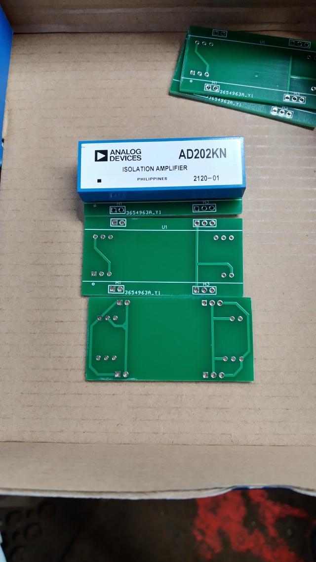
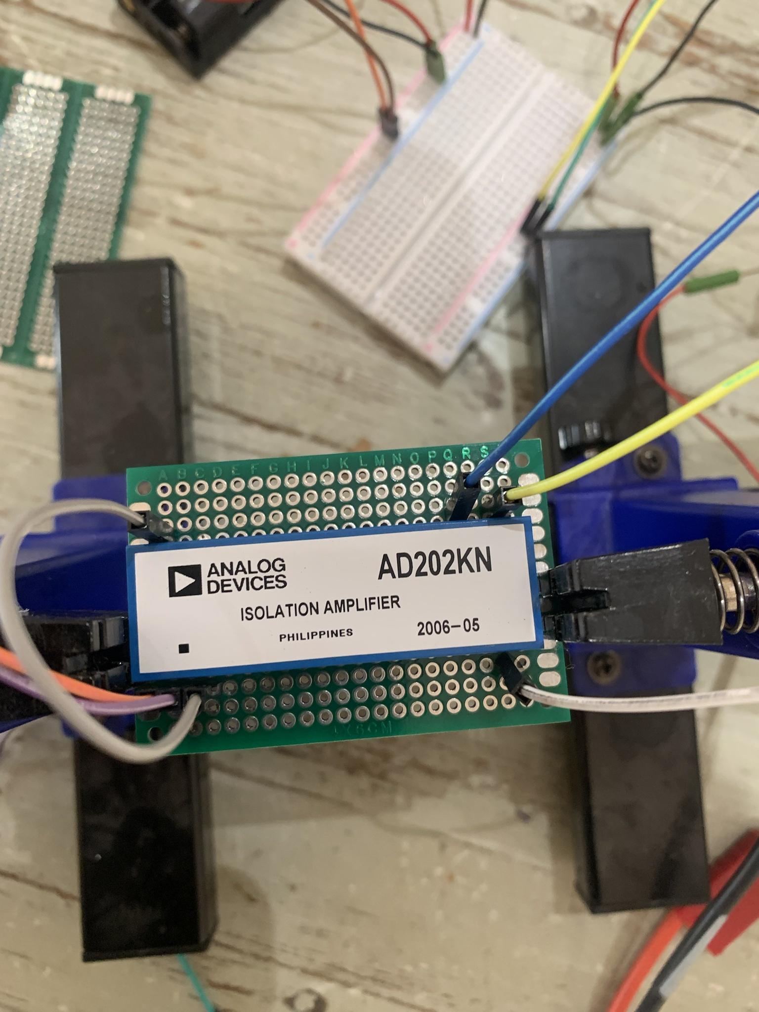
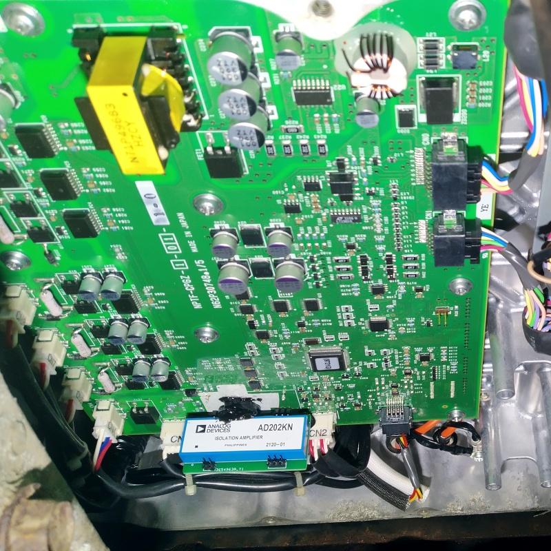
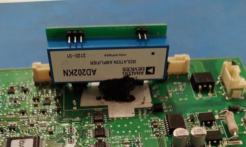
My AD202 got to Edinburgh this morning so hopefully I'll see it tomorrow. The simple pcb I designed and ordered from China is in transit, last tracked in Germany so I should get it Monday. I'll have 4 spares I can post, I'll test mine first. I missed out the 2k resistor :shock: but I'm going to try without it.

When the isolator is not powered, a negative input voltage of more than about 2 V will cause an input current to flow. If the signal source can supply more than a few mA under such conditions, the 2 kW resistor shown in series with IN+ should be used to limit current to a safe value. This is particularly important with the AD202, which may not start if a large input current is present.

From what I understand they are saying that if the HV side gets powered before the 15 volt supply it can cause problems. However I don't think we could ever see this as the precharging only happens after the ignition gets switched on. So the AD202 will always see 15v before HV.

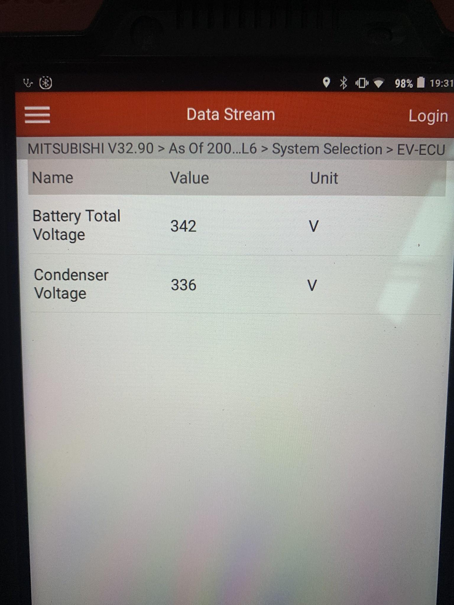
EDIT: 400 volts through 600k ohms is well under 1mA, we'll never get anywhere near 2mA across pins 1 and 2.
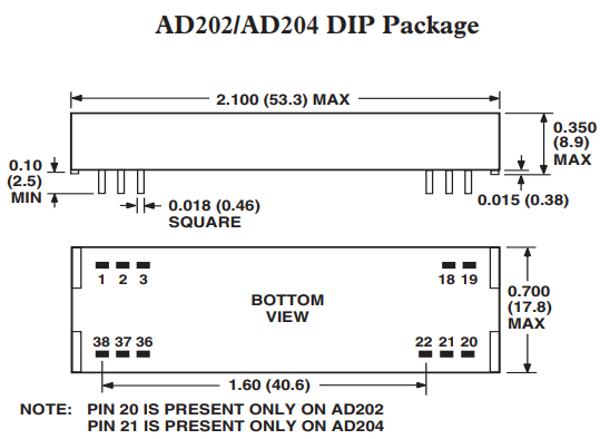
 
kiev said:
but one thing that concerns me is that little chassis ground symbol hanging off of pin 2 inside the diagram--i don't know what that means.

Figure 1a on the data sheet also shows the chassis ground symbol, I don't think it is relevant for the connections.
 
I've got my AD202 and PCBs from China! :D 
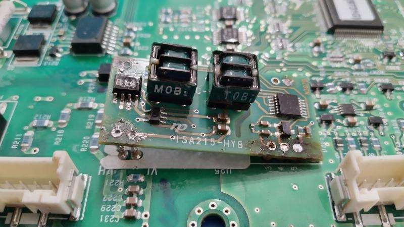
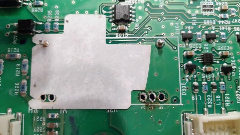
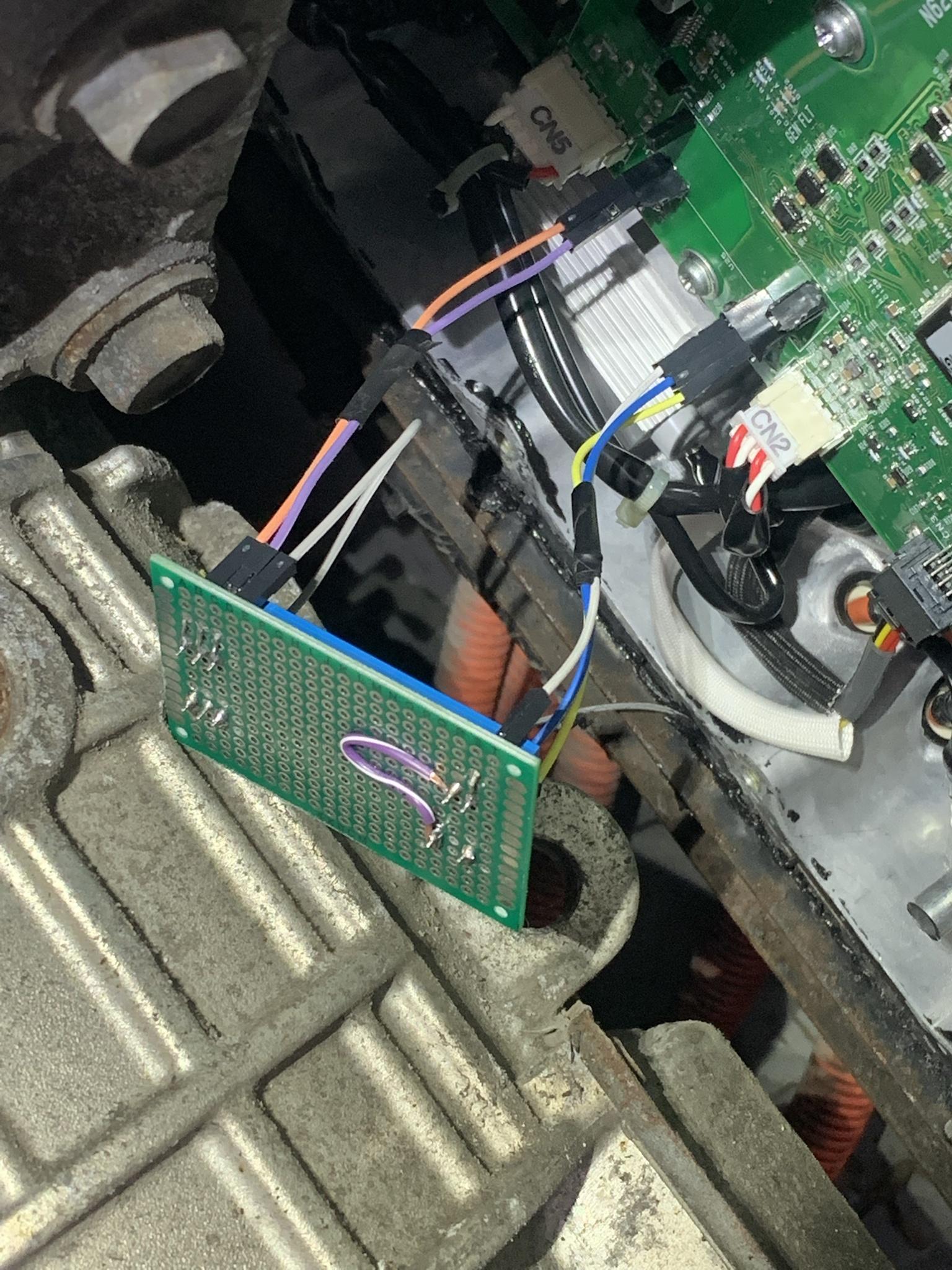
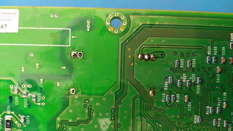
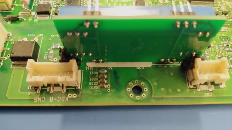
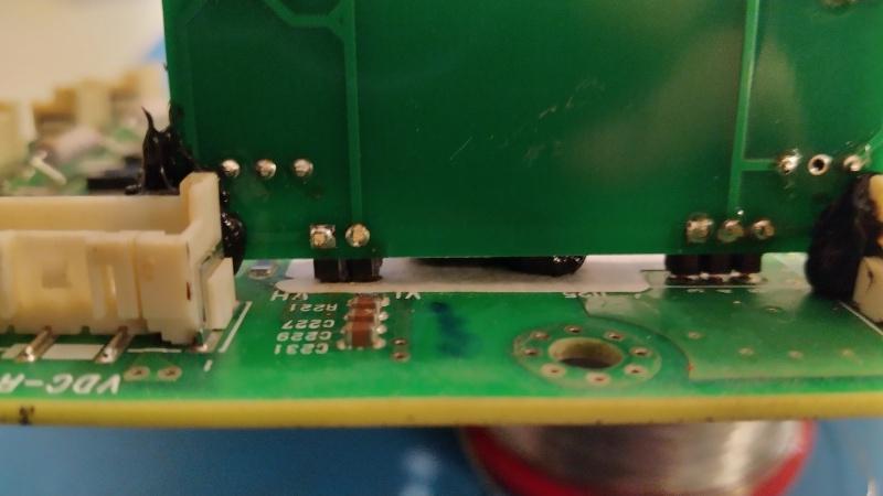
Now to check that I got the layout correct. :shock: I'll solder it in tonight and try it on the car tomorrow. Spent last night desoldering the hybrid board. My TS100 at 19 volts wasn't really up to the job, particularly with pin 4, the main circuit board has a large ground plane that just sucks the heat away. I'm sorting out a 24 volt supply so the TS100 can use it's full 65 watts. I'll post an update this evening.
Yh5HV2O.jpg


xJQ1024.jpg


gx2LwIZ.jpg
 
*************************Well perfect news for a change not just good news***********************************************

I will update my previous post as I had the wrong pins due to the AD202KN being a dip package when it arrived.

My installation is very temporary to test but the input and output readings are perfect now.

My AD202 is on a solder board but in an ideal world Greg's idea is superb.

I am going to mount it on the bottom casing cover and fly-lead it to my pins on the main board, all not perfect but good for my fix.

I have another spare MCU which I have programmed to match the vehicle and will get another AD202 for it.

This is the end of this problem until the next!!!!!

h8pLhbj.jpg


cPPVewG.jpg


IkmjZzn.jpg


4620Z3B.jpg
 
Here's my board refitted looking pretty.
bw4wy4k.jpg

To bad it doesn't work! :(

I've got different symptoms now. Previously the condenser voltage live data stayed at 0 volts all the time. Now when trying to start I get an over voltage fault and live data shows condenser voltage staying at 420 volts (battery voltage live data shows 355 volts). I took some quick voltage measurements and read 0 volts at the high voltage side, 14.9 volts to the supply and 0 volts on the output. So I rechecked the condenser live voltage and it now showed 0 volts. Very strange, then I noticed that the condenser live data started to jump around a bit, the voltage will climb and then drop back to 0.

So to recap, when trying to start, live data jumps to 420 volts setting a voltage fault, it stays there for around a minute then drops off to 0 volts, occasionally climbing up to maybe as much as 80 volts, sometimes 30 volts or maybe only a few volts, and then dropping back to 0. I'll get 2 volt meters accross the AD202 and compare actual readings to live data, but it might be next week before I can get back on it. I've also rechecked my board layout with the pictures in the previous post and all seems to be okay.
 
boothegermanshepherd said:
Hi

**************** EDIT ****************************

My AD202KN arrives today

just checking the configuration and a question about pin outs

going by the datasheet I can see the pins as follows but can I use pin 32 and 37 both as common for the 15v return?

Main board AD202Kn


pin 1 VH pin 1

pin 2 VL pin 2

pin 3 signal pin 36

pin 4 12v rtn pin 22 and 37

pin 5 vcc 12v pin 20

pin 3 and 38 on AD202 bridged

Using the pin assignments from the data sheet.
r0SgV0D.png


Shouldn't pins 3 and 4 be as follows?

pin 3 signal pin 19

pin 4 12v rtn pin 22 and 18
 
Sorry Greg, hopefully I have put it my previous post right now!?

I had the same problem but it was because I didn't bridge pins 3 and 4, again I misread that this had to be done, I thought this was just an option.

I like your fitting to the board!

So just refitted everything with my new board bonded to the bottom cover with 5 fly-leads and apart from being 6v difference no problem. From previous diagnosis and testing it took at least 12v difference before "no ready" would occur.

I would be interested if anyone else can give the two live data voltage readings out of curiosity especially if there board is still original.

GS4Dn61.jpg


7EPjgu1.jpg
 
boothegermanshepherd said:
Sorry Greg, hopefully I have put it my previous post right now!?
Previous post looks good. The data sheet is confusing because the pin numbers on the example are for the SIP package, that doesn't seem to be available. You have to use the conversion chart for the DIP pin-outs.

boothegermanshepherd said:
I had the same problem but it was because I didn't bridge pins 3 and 4, again I misread that this had to be done, I thought this was just an option.
Thanks for this info, I have the pins bridged but I am suspecting that I should have used thicker tracks. If this is the problem it's easily rectified with some bodge wires on the back of the board. Did you use the 2k resistor mentioned in the data sheet? I didn't see one in your pics.
 
@Greg: it looks like your op amp is damaged on the ISA board.

Live datastream reading from my 2012:

Battery Voltage: 356

Condenser: 354

Battery Current: 1 Amp


Make sure those fly wires are secured or even soldered into place--don't want anything coming loose while driving...

It is confusing with the diagram for the SIP with different pins than the DIP, i'll do a markup diagram and repost it later.
 
Good evening

I didn't use the resistor or the cap between the bridge

I dont think its your tracks as they look on par with the original, also mine is only connected with jumper leads. Did you try it on the bench first? I did as I was concerned about using the same ground - on both pins

I have secured the fly-leads with a bonding sealant used for fitting car panels and pasted the rear of my board with it, after it had cured I then used the same agent to fit it to the lower cover. When this was cured I plugged it in and put some blobs of good quality sealant on those pins.

I have ordered some plugs with fly-leads and pcb sockets to do a better job on my spare MCU.

Im not to concerned that my voltage is 6v less but wonder if I should have rear the data sheet more into being able to give it a gain?
 
The AD202 datasheet gives the gain error as +/- 0.5% typical, 4% max.

Your bench test showed an 18mV difference, which is the -0.5%, and this would equate to -2V on the Condenser voltage reading.

On my car there was a -2V difference, which is likely normal for having the car in READY with the DCDC converter working. So that accounts for -4V of your -6V in the livestream data. As long as it stays that way and the car runs then it might not be worthwhile chasing that missing 2V.

You could add some gain with a feedback circuit, would probably need to use 0.1% resistors.

Also could change the 6.8k resistor on the main board to 6920, and that would cause the pack voltage to equal the condenser voltage at your 342/336 conditions. When the car is moving and there is normal driving currents from the pack, i think the condenser voltage will show a greater difference, so not sure how significant or critical it is...
 
That's a good data point.

The ISA215 gives the gain error as +/- 1% with another .5% due to nonlinearity.

Your -6V is about -1.75% error.

Seems too much coincidence to be the same difference with both types of isolation amplifiers?
 
Rt5JmxM.jpg


Success! :D :D Turns out the problem was an assembly error, spot the problem. :roll:

RX5M1c5.jpg


I'm seeing the same 6v lower condenser voltage as well. There is a trim circuit in the data sheet but I'm not sure it would be worth the trouble. I would suggest testing this and seeing if any problems develop. The fact that my board shows the same 6v drop as @boothegermanshepherd is promising.
 
Here's some more pictures of my installation.
9sWMP3n.jpg

DKzENgC.jpg

WfhTDwh.jpg

I'm going to put another blob of sealant at the top of the board so it bonds with the lower cover. My concern is that the solder joints could crack due to vibration so hopefully the sealant will prevent this from happening.
 
Well done

I am glad I mounted mine flat on the base cover as I was concerned about the security like you have it, what happens if you bond it to the lid and then have to remove it!!!!!!!!!!???? Just a thought

I wish I took some pictures now

Im reassured now with your voltage readings :D
 
boothegermanshepherd said:
...what happens if you bond it to the lid and then have to remove it!!!!!!!!!!???? Just a thought

I'm just using automotive gasket sealant, it should peel away if the cover needs removing in the future.
 
GregFordyce said:
boothegermanshepherd said:
...what happens if you bond it to the lid and then have to remove it!!!!!!!!!!???? Just a thought

I'm just using automotive gasket sealant, it should peel away if the cover needs removing in the future.


Good job and If your like me I'm confident now the lid isn't going to be coming off again!"
 
Back
Top