Distribution of cells in the pack.

Mitsubishi i-MiEV Forum

Help Support Mitsubishi i-MiEV Forum:

This site may earn a commission from merchant affiliate links, including eBay, Amazon, and others.

Malm

Well-known member
Joined
Jul 22, 2013
Messages
452
Location
Tábua - Portugal
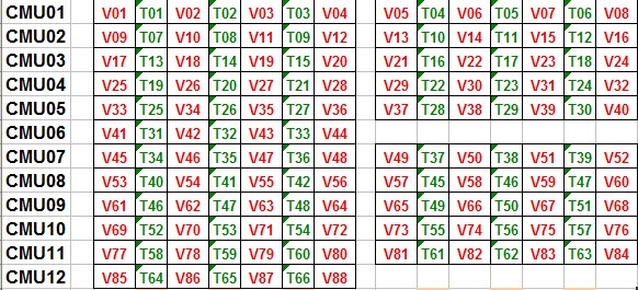
I tried to locate the 88 cells in the pack. This is my result.

bdyz.jpg


Green are cells that discharge slower in my i-MiEV, red those who discharge faster, as seen at 14,5% SoC by Canion.

What do you think, i'm far of the reality?
 
Interesting ...

If your supposition were true, would suggest that the lack of refrigeration makes them suffer more inner cells than the external ones.

The distribution has a shape similar to that, but I have not clear if your numbering of the cells is correct.

Only for refresh:

p3_img1.jpg


mitsubishi-i-miev-battery-pack-photo-335601-s-1280x782.jpg
 
"If your supposition were true, would suggest that the lack of refrigeration makes them suffer more inner cells than the external ones." Yes, that´s what i'm trying to prove. My cells 19, 62, 63, 71, 73 discharge faster because they are always hot, and time makes them suffer for this.

"The distribution has a shape similar to that, but I have not clear if your numbering of the cells is correct." I don't know either if i found the right distribution, but i think i´m close, very close.
 
I think you made a good try but you have the layout and the connection sequence wrong in both blocks. If you flipped the whole numbering system of the left block so that #1 is in the lower left corner, you should be getting closer. That is the most negative battery module. If you look at the picture of the pack you can see the buss bar leaving the contactor and going over the second battery and up to the far end of the first battery---it's really hard to see in the photo in the post following yours as it is a protype JDM pack and not exactly the one in our I-MiEV's. On your diagram, the lower left corner would be #1. The cell numbering increases left to right in the entire block (i.e. cell #1,9,17,25 and 33 are on the left side of the block) Numbers 41 thru 44 are in the drivers side 4 cell module (with #41 on the top in your layout). The power leaves the 4 cell module and goes though the HV lockout switch before going to the right block. In the right block, cell numbering increases right to left with #45 in the upper right corner of the right block. (cell #45,53,61,69 and 77 are on the right side of the right block. 85 thu 88 are in the final 4 cell module on the passenger side (with # 85 on the bottom in your layout. I hope this makes sense.
 
pv2q.jpg


I found the 40 who are in the front, just have to rotate them 180º and those who are in the rear, just have to do the symmetric. I also found the 8 that are in the middle. I knew that i wasn´t far. My "red" cells still appear in the center of the two forty cell groups, so I will continue to explain my weakest cells by being hotter. Thank you siai47. I think this distribution makes sense.
 
It looks much better---only one minor problem. The two four cell modules need to be switched in position top to bottom---41 thru 44 on the top and 85-88 on the bottom---then it is correct providing Mitsu numbers the cells from negative to positive (which is how I think it is done). Your drawing looks pretty much like a heat pattern you might expect with no airflow within the pack. If you see a "hot" cell in a location where the other cells are cooler it might be indicitive of a weak cell (or a lower capacity cell). As the cells age, internal resistance builds up causing more heat buildup during charge/discharge cycles. I still don't trust the sensors in the pack. If the pack has rested for 24 hours, the canion shows all the sensors reading the same (ambient) temperature. As soon as you start to discharge the pack there is a strange pattern of temperatures going up (like a step pattern) in three cells then repeating. The canion shows some very weird spikes on some of the cells that don't make sense. It shows up in the same area on cars other then mine. I am also not sure exactly where the sensors are within the module. There are six in the eight cell modules and three in the four cell modules. However, when I took a eight cell module apart I couldn't figure out what was going on as one half of the module looks like there are more sensors then on the opposite half. I have pictures---just not good at posting them.
 
It looks good to me now. I guess I shouldn't refer to drivers side or passenger side because a lot of people live in countries Napoleon didn't conquer. I've heard that Napoleon changed the laws in conquered countries so that when passing on horseback, the riders passed left side to left side so the hands they carried weapons in (usually right) were on opposite sides. Made it harder to surprise the passing rider. So I blame the mixup in the battery layout on Napoleon. Still doesn't explain why we have left hand drive cars in the U.S :? !
 
We can blame Napoleon for the confusion on where to place 41-44 and 85-88. But not for the inner cells being more affected. I wish i could change the position of cells twice a year, like we can do with tires :roll:. Always ahead in time, i think.
 
Bonjour,
according what we get from the CANBus, here is my opinion about the distribution.
(anyway, this is the way canion is working...)


bmu_V_T.jpg


Red: individual cell Volt
Green: Temps

But I have no ideas about their places....

Each CMU manages 2 packs , But CMU06 & CMU12 manage only one pack. (confirmed using the service tool).
 
priusfan said:
Bonjour,

Each CMU manages 2 packs , But CMU06 & CMU12 manage only one pack. (confirmed using the service tool).

Hola,

There are 10 x 8-cell modules (aka CMU 01-05 & 07-11?) and 2 x 4-cell modules (CMU 06&12?)

1 pack for CMU, I understand.

8-cell module:

Yuasa+LEV50.jpg


4-cell:

lithium-ion-batteries-12414-5830847.jpg


Although 8-pack can be 2 4-pack in series ¿?
 
priusfan said:
Bonjour,
according what we get from the CANBus, here is my opinion about the distribution.
(anyway, this is the way canion is working...)


bmu_V_T.jpg


Red: individual cell Volt
Green: Temps

But I have no ideas about their places....

Each CMU manages 2 packs , But CMU06 & CMU12 manage only one pack. (confirmed using the service tool).

I found that distribution of sensors some days ago:

gy31.jpg


but the location that you give is more precise, so a very good contribute, thank you.

What you show is 100% compatible with the distribution proposed by me and Siai47:

7thb.jpg
 
I know that there are some citroen C0 or Peugeot Ion that only have 80 cells. I suppose they miss cells 41 to 44 and 85 to 88. Anyone can confirm that?
 
Back
Top