The Troubleshooting and Repair for On-board Charger (OBC) Thread

Mitsubishi i-MiEV Forum

Help Support Mitsubishi i-MiEV Forum:

This site may earn a commission from merchant affiliate links, including eBay, Amazon, and others.
BlueLightning said:
10 W
4.7 Ohm then Imax = 1.5 A, or Umax = 6.9 V
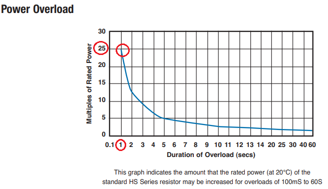
They actually will get up to ≈170 V briefly, so a massive overload: P = U²/R = 170²/4.7 = 7225 W, or a 723x overload! I suppose one should use RMS values, so that's 120²/4.7 = 3064 W = 306x overload. I would prefer to see a resistor with a high peak power rating, usually these are aluminium clad (though the aluminium is little to no help, since the pulse of power is so brief). Even these resistors are only rated for 25x nominal power. If you use just one 10 Ω resistor, that's 240²/10 = 5760 W, so really you'd need a 250 or 300 W nominal part. Those are pretty large! Probably a 200 W nominal part would do, because the power decays so quickly. The stock resistors seem massively underrated for what they do.

Edit: example of a resistor that is rated for 25x nominal power for 1 second:
https://www.digikey.com/en/products/detail/te-connectivity-passive-product/HSC20010RJ/2366393

Zero stock of that particular part as I type (parts shortage, not just semiconductors), but there are several other suppliers.

AvcX1bx.png
 
That's potentially some crazy overload if the relay doesn't engage.. :eek:

The Nissan laef uses 3 of those ceramics to do the same function, notice the similar layout of the board

g2N30PI.jpg
 
I got my new parts delivered yesterday and soldered them onto the board. I changed the defective resistor, the relay and the snubber caps.

I reassembled the OBC and got the exact same problem again. The fans are turning on for a very short time and then the charging stops.

I can measure the 12V going into the top board from the AUX battery.
 
Unfortunately I did not check the waffle plate, but I did not notice any visable damage here. Can you think of anything else to check while the OBC board is in the car or should I remove it again as my next step?
 
Check the continuity thru to L and N again in case the resistors may have gotten damaged. verify that the relay is working and good again.

There are no good test points to grab, so some folks have soldered fly leads to those terminals such that they could connect a DMM to measure if the mains AC is getting to the L and N terminals during a plug in session. If the EVSE is getting the start command and sends the AC, and it reaches those terminals but the session halts, then the waffle plate is likely damaged.

The diode drops can be checked with the board in the car, but the faston terminal connectors all have to be disconnected, and it may be more convenient to just remove the board and take it inside if the weather is rough.
 
Due to several changes of those resistors I saw behavior that charging doesn't work after repair. It happened because of errors in car, even if car doesn't show check engine.
 
So I was away for a few days and got finally back trying to repair the OBC. I tried to delete the error codes and the car now behaves differently when I plug in the charger. Now absolutely nothing happens, there are no fans spinning at all but the light on the charger turns on for several seconds before going off again. The new error code is the same as the one before. The resistor and the relay is fine and the EVSE connects the 230V to the OBC.

I tried to measure out the waffle plate but got one question here. I used the picture with the diode drops linked from the first page and there are these resistors on the bottom right side. Can I just measure the resistance between those points? Because when I for example tried to meaure the two 1k resistances I only got 200 Ohms there.
 
Make sure that the tiny contacts of the flat ribbon cable are inserted correctly.

Check that the connector into CN101 on the top control board is seated fully.

And make sure that all the external connectors and connections that were removed have been made.

There is a better schematic of the waffle plate in post 3 on page 1. It doesn't have the diode drop voltages but shows the resistors on the board that connect to the solder junctions. i measured the drops on a bare waffle plate. With the plate installed there are some parallel paths that may prevent reading the resistor values. If all the diode drops are good then the waffle plate is likely okay.

Also in that post is a pinout list for CN101 showing the 12V Hot all the time and the Switched 12V. Clip on a voltmeter and verify that those terminals have the proper voltage. Don't try to hold probes--if you slip it can cause severe damage. If they do then check the voltages on the 8 electrolytic capacitors on the top control board.
 
So I checked the waffle plate again and could not find any isseue there. I soldered thin wires to C101 and could read the battery voltage there. All voltages on the caps match the voltages measured by skylogger.
 
Do you mean the two orange cables going in the top board? I have mains AC going in there, but that was also the case before.
 
No i'm was talking about the solder junctions "L" and "N" of the waffle plate in the schematic of post #3 on page 1. You replaced the white resistors, did you check or replace the relay? Check continuity for " L" and "N" in case the resistor has opened up again after power was applied.

check/verify that the flat ribbon cable is inserted properly and that you have continuity thru each contact from control board to the power board.

Also in post#3 is a pinout list for the CN101 connector, verify that the 12V hot all the time and 12V switched are getting voltage. If they are then check the voltage of each of the 8 electrolytic capacitors on the control board.

Please read all my posts on page 1 (especially post #2) and follow the links for details.

If AC is reaching the waffle plate but charging is not started, then there may be a fault in the AC detection circuit on the power board, or the low voltage power supplies on the top control board.
 
To Szet:

I fully agree with Kiev and specially on this part:
"check/verify that the flat ribbon cable is inserted properly and that you have continuity thru each contact from control board to the power board."
The flat ribbon cable and its connectors are extremely delicate and so too easy to be damaged or not properly connected. Pls check carefully.

Then do you hear the click of the relay?
 
Thank you for alle the help. I just checked a few things like all fuses etc again and some other stuff on the OBC. Here is the summery of all that:

The car is not charging, but I get voltage on the orange cables into the OBC. One of the big ceramic resistors was open circuit. I replaced both resistors, the snubber caps and the relay. I also checked the ribbon cable and the connectors. The waffle plate shows correct voltage drops. The caps on the top board seem to have the correct voltage. I also double checked IC710 and IC718 on the top board, they generate their correct voltages. I get 238VAC between L and N on the waffle plate but the relay does not open. I soldered myself to the 5V on the top board (pins 25 and 26 on the ribbon cable) which should open the relay and tried to charge, but the 5V do not come on at any time. 12V hot is always available and 12V switched comes on when trying to charge.

Any thoughts on where to go from here?
 
Do you mean to "close" the relay rather than "open"?

Just because you close the relay with an external 5V source doesn't mean that the charging will begin. The microcontroller on the top board monitors and controls the functions of the OBC; if it is not getting the correct range of signals that it expects, then it will prevent charging and throw a code.

If you try to bypass the built-in protections then you will likely cause additional damage to whatever was the original culprit. So that is never recommended.
 
Of course I mean to close the relay, sorry my fault. I did not bypass the relay. I just measured, if there are 5V at any time there, but the microcontroller seems to stop the charging before opening the relay.
 
@Szet,
I would check -with no power-:
-if there is continuity between the collector of TR301 and one side of relay coil,
-If there is the continuity between the 5 V on C703 to the other side of the relay coil.
-if the TR301 (NPN) is OK (the emitter is grounded, Collector is central pin)
-Check the D301 which is in parallel to the relay coil.

-While trying to charge-:
-If the VBE of TR301 is some 0.7V when charging
-If the VCE of TR301 is almost 0V when charging
-if almost 5V reaches the relay coil when charging

I hope to have been of help for you.
 
hello avryone
I want to bay new parts for Onboard charger.
1) resistors with thermal fuse
2) The Waffle Plate

if you can help me, please give me links where I can bay this parts.
I do not know "The Waffle Plate™"-s real name to search it on ebay or enyware.
 
We didn't know the official name--that's why we just made one up. But nobody else knows it either. :lol:

The early model nissan leafs use the same waffle plate in their OBC, e.g. 2011 and 2012 models where the OBC is mounted behind the rear seat. Get one out of a salvage yard and harvest the plate. And the resistor with the thermal fuse.
 
Back
Top