Frud
Active member
The mode of use of NMC elements in solar systems and in transport differs significantly. In transport, the load current can suddenly change to limiting values and the voltage difference in individual elements can be significant and also accumulate over time. Therefore, in transport, balancing of elements is necessary.I'm using a 2015 Zoe NMC pack in my solar storage and specifically got a 3rd party BMS capable of actively balancing the cells. I disabled the function to see how much they drift over time; could have saved that money, the cells are still within the same 3mV after a year of daily use.
Similar with my wife’s EV, it’s NMC cells are still perfectly in sync after nearly a year (I rarely charge to 100% to start it’s balancing routine).
I therefore recon the native balancing function (that was struggling with LEV50x) will be well capable of keeping the NMC cells in line for years to come??
As regards to 88 vs 80 cells, it’s just one parameter that can easily be changed, so unless there are other advantages using cell instead of pack voltage I’d leave it as it is…
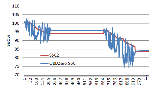
You're right. Determining true SOC works better when using low cell voltage. I also wanted to use this option. However, I didn't know that the value of the minimum cell can be obtained directly, rather than sorting the results of reading an array of all cells. This is expensive in terms of CPU time.This has got me to thinking about how to convert as much as possible in the code to integer arithmetic. It's a good idea but right now it is best to limit the changes until we have something running dependably.
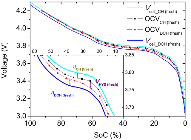
However there is one thing I'm wondering about. In PID 0x373 byte 0 is the the highest cell voltage and byte 1 is the the lowest cell voltage. If we use these to compute the SoC based on voltage we can avoid the problem of 80 cell and 88 cell cars. We can compute the average of the highest and lowest cells and this will be very close to the average of all the cells. On the other hand the lowest voltage may in fact be the right value to use. As the cells are in series then the maximum Ah that can pass through the battery is equal to the Ah in the weakest cell and this is the cell with the lowest voltage. Any thoughts anybody?
Is it possible to obtain the internal resistance of the battery as well? I saw this value on the OBDZero screen. Is this a constant or does BMU actually calculate the internal resistance value using its algorithms?