tewharaunz
Member
I’ve been having 12v battery problems and (I think) I have read every post in this topic area and haven’t found anyone with the same issue.
Replaced 12v (aux) battery with Lifepo4 (drop-in replacement with BMS).
Had no problems for a week of daily type 2 charging (commute is 80kms)
After long weekend (4 days without charging), aux battery battery stopped (low voltage protection).
I put a 12v charger on it for 15 minutes, and that was enough to “wake it” but it cut out again at work and I had to pull it and charge it in my office.
During a type 2 charge, the aux was ~14v and after it was 13.3v.
When I got home (turned off) it was 13.07v, and when I turned it back on (ready), it was 12.9v.
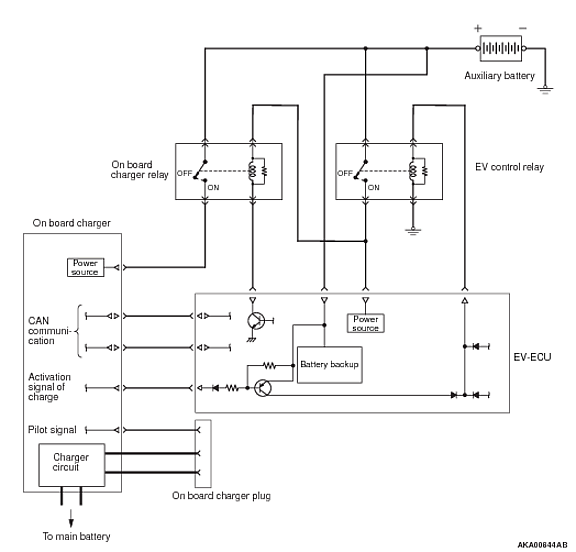
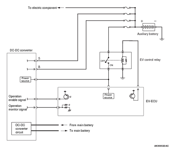
Does anyone have any experience with their aux battery not charging in ready mode, but charging fine when plugged in?
I’ve looked through the service manual for likely fuses, but nothing has jumped out.


