No READY. P1A15 error. Condenser charge timeout.

Mitsubishi i-MiEV Forum

Help Support Mitsubishi i-MiEV Forum:

This site may earn a commission from merchant affiliate links, including eBay, Amazon, and others.
If just for testing purposes, then sure, some of them could be bypassed with a jumper wire in order to get the signal down at VH below 5VDC.

But not for a long term solution.

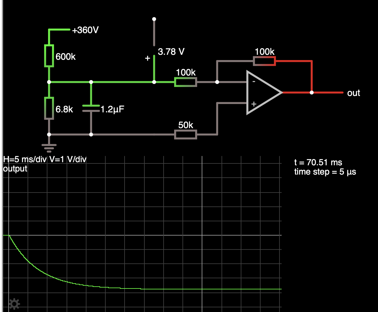
Here's an idea to test while you are waiting for parts: if you have an extra AD8677 op amp, wire one up by itself on the bench in a bread board or dead bug wire it, with +5 and -5 supplies, then apply input on pin 2 with pin 3 grounded; apply 3, 3.5, 4 volts thru a resistor to pin 2 and observe if it gets pulled back down to 3.5 when the input is higher than that. If you don't have enough power supplies, just use +5 and return for supplies since you are only testing the input with a positive signal if should still bleed off the excess.

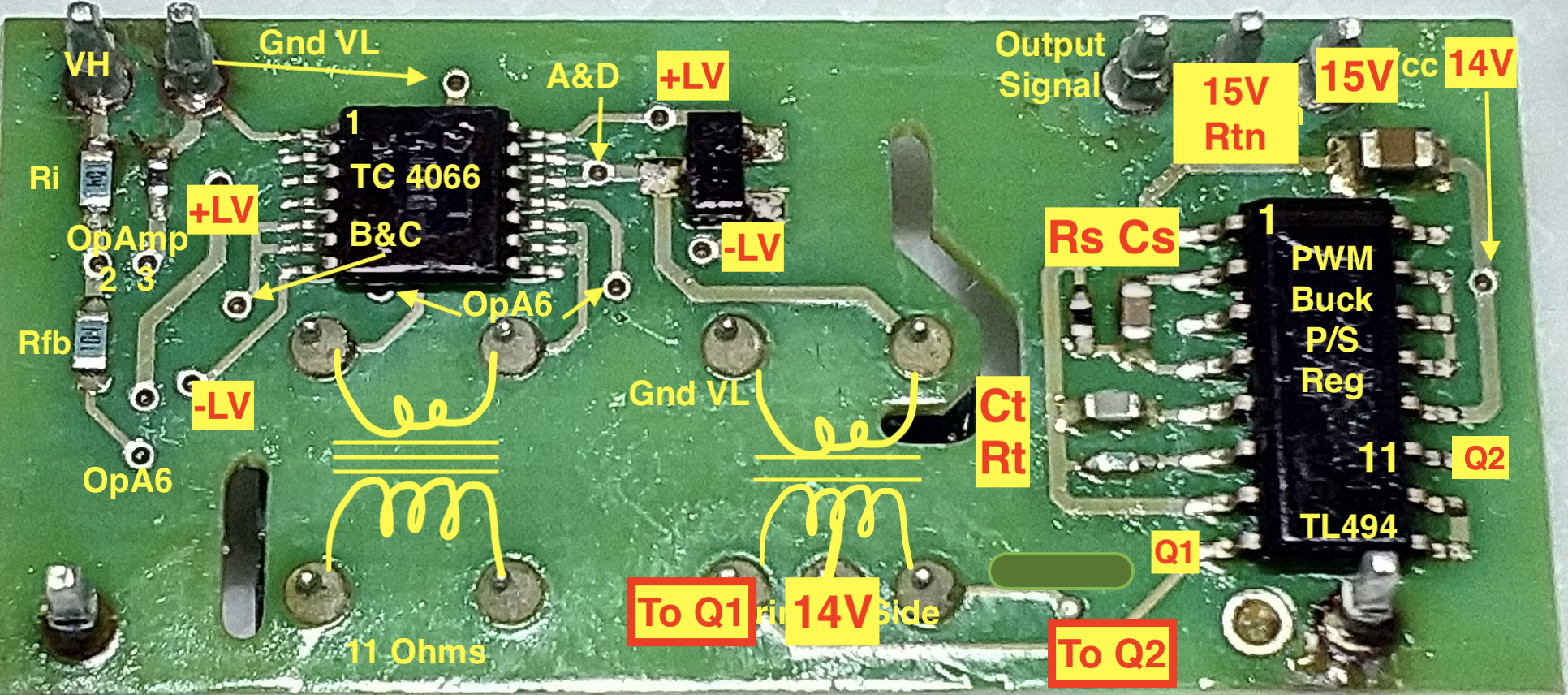
i was quite surprised to see all the hidden vias under the PWM chip.

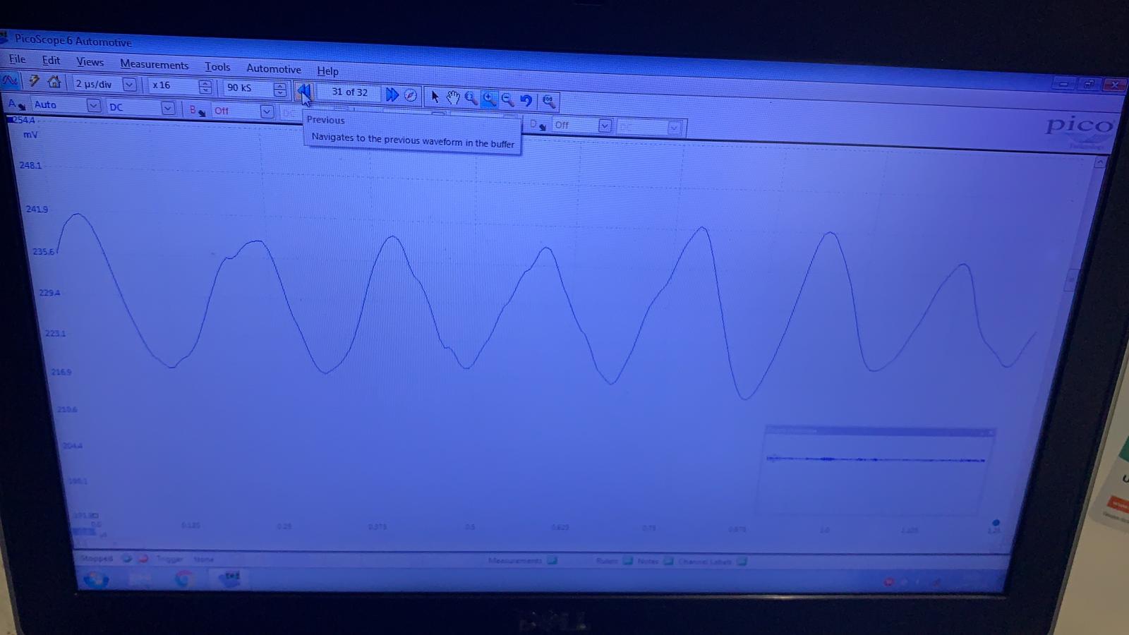
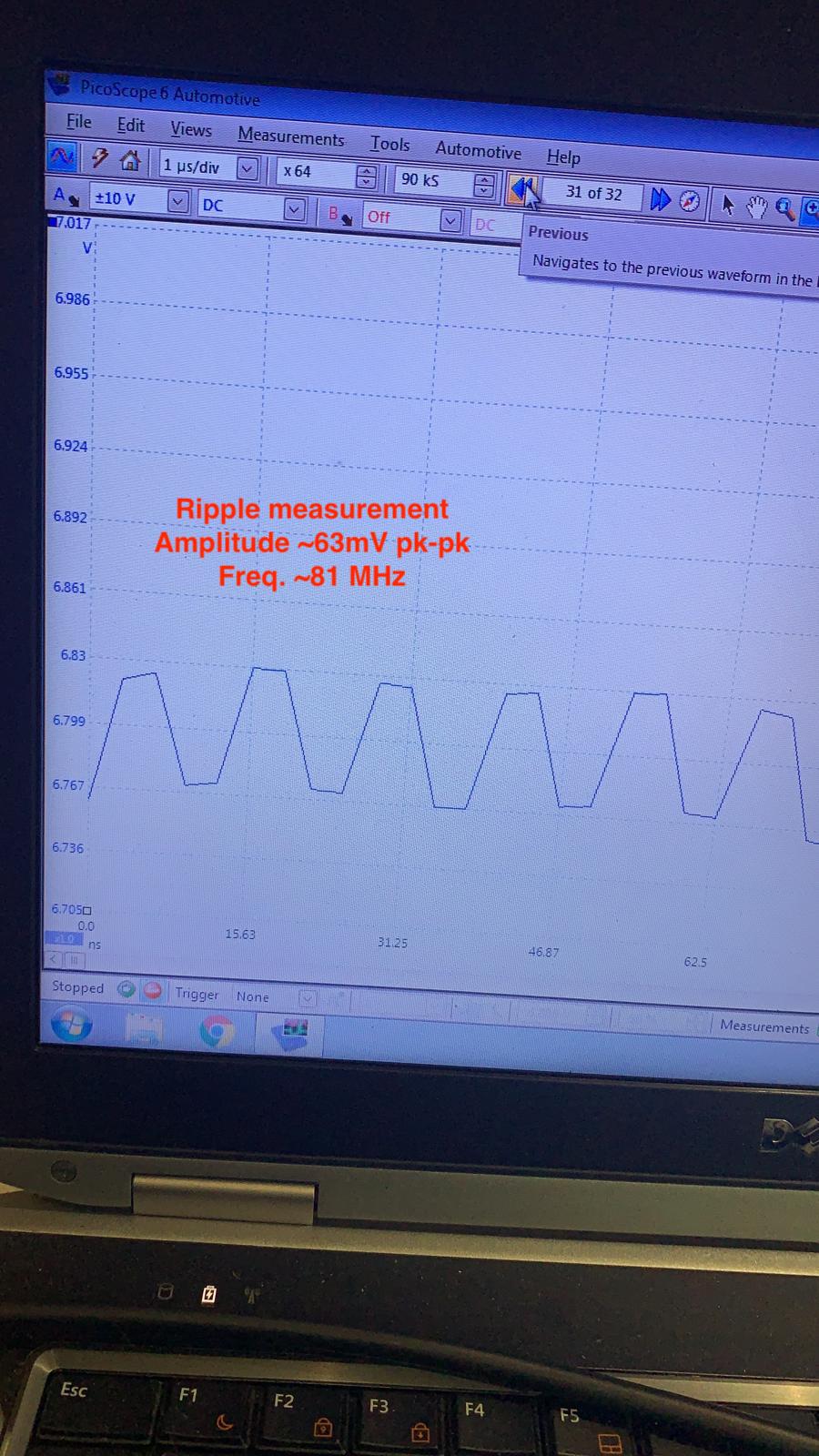
The hash in the + and - supplies is occurring at 50 and 100 Hz, so i suspect that noise is from the mains frequency, the burst width is about 6msec.

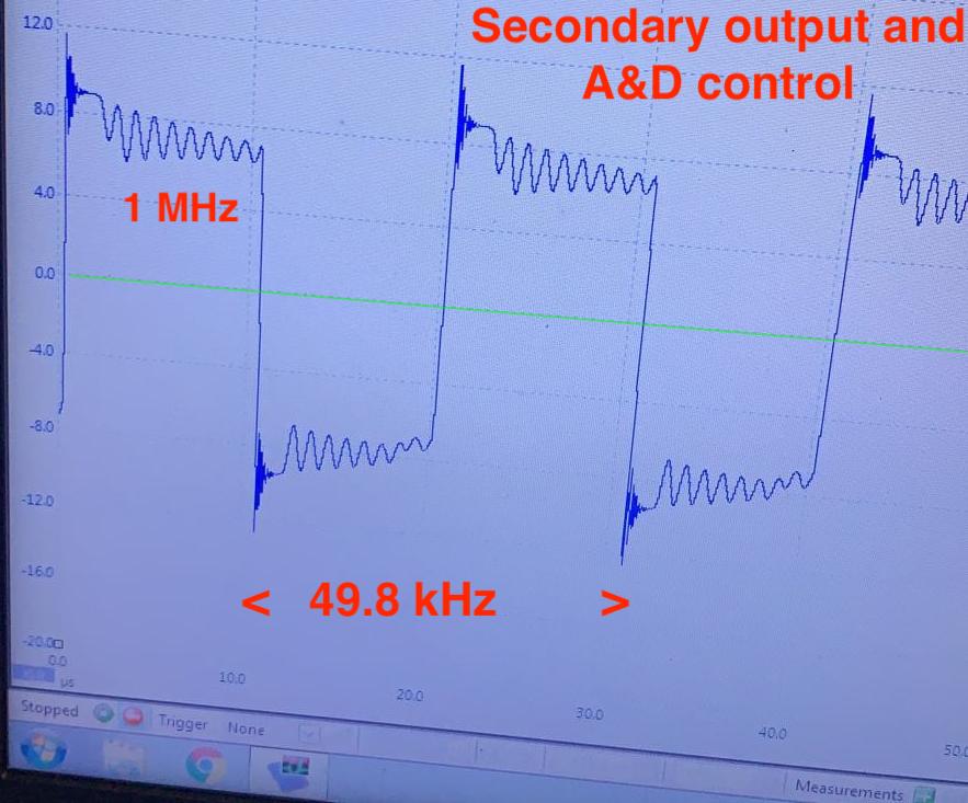
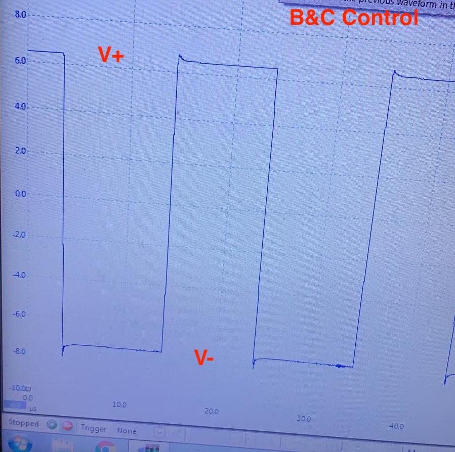
The switch control lines AD and BC are at about 53kHz, which is the expected frequency from the PWM chip, so the little resistor and capacitor on TL494 pins 5 and 6 are doing their job. The waveform appears symmetric so the deadtime control is not out of whack.

Just looking at the small band about the mean it would seem the ripple is about 130mV.

If the op amp output on pin 6 is the inverted equal to the input on VH, then it is likely working okay and no need to disturb or swap it out--the problem seems to be downstream of there, such as the 4066, or the signal transformer, or the output 4066 and LPF.

There are no easy access vias for test points for the other end, but that all needs to be checked also to find out where the voltage leak is happening.
 
boothegermanshepherd said:
I have ordered a handful of op amps to test
I have ordered:

Standard Items Ordered Reference: 163665140
ICL7611DCBAZ Renesas Electronics, Op Amp,
Oh. I thought I made it clear that we need the 7612, not the 7611. The 7611 is worse than the AD chip, I think. I hope it's not too expensive.

If your supplier doesn't have them, then you needed another supplier.

But Kennedy doesn't like the idea of an unknown chip, and the focus is now on the supply rails. So don't bother getting the 7612s, at least at this stage.

I'm not convinced that the AD chip input is dragging down the resistive divider. What is the input resistance of your multimeter? Maybe you can read it with another multimeter on ohms range. If it's less than the usual 10 Mohm, it might be loading down the divider.

Maybe disconnect the divider from everything else, including capacitors, and add them back one by one to see what is loading it. You might have to get a bit creative so as not to damage the PCB (e.g. by cutting tracks).
 
Hi coulomb

So the chips I ordered are not suitable, no problem as long as I know before I fit one.

Shall I get 7612 for when we need them?

I am very new to in depth electronics so you will have to be gentle with me!

I am not understanding which resistance your asking me to check and also which is the divider?
 
boothegermanshepherd said:
50v ac

Just another test I have done

Is to apply 30v dc to pin 1 of cn4 as it’s as much as my supply will do!

Tracing it through the wiggly row of resistors it drops about 5v on each until hv and it is then 315mv on the input

The output on pin 3 is 301mv

If you had exactly 30V on CN4, then the voltage divider created by the string of resistors should have resulted in 336 mV at the VH input..?
 
boothegermanshepherd said:
Shall I get 7612 for when we need them?
No. Your latest test with 30V shows that the problem isn't input voltage getting too close to the positive power supply.

I am not understanding which resistance your asking me to check and also which is the divider?
All measuring devices affect the system that they are measuring to some degree. For a voltmeter (or multimeter on a voltage range), it's due to its internal resistance. In the old days, the current drawn was used to power a moving coil meter. In modern multimeters, there is an input amplifier that presents a high but not infinite resistance to the circuit under test. If that circuit has a high impedance, then it can significantly affect the reading.

Multimeters typically have a 10 megohm (10 million ohm) resistance. Suppose that the circuit under test consists of two one megohm resistors in series across a 10V supply. This is called a voltage divider. The expected voltage fraction is the resistance of the lower part divided by the total resistance. In this case it's 1/(1+1) = 1/2 = 0.5. So we expect to see exactly 5.0V at the middle. With a 10M multimeter across one of the 1M resistors, the effective resistance changes from 1.0M to 0.909M (10/11 M). So now we measure 0.909/1.909 x 10 = 4.76V. That's 4.7% lower than actually present before the measurement. Note that you would read the same across the top resistor. Yet the power supply still reads 10.0V. It's as if voltages of things in series no longer add, but it's all because of the measurement disturbance.

It's possible to estimate the error by comparing impedances (in this situation, impedance is the same as resistance). The voltage divider has an impedance of 0.5M (the power supply has a negligible impedance, so the two resistors are effectively in parallel for this calculation). The resistance of the multimeter is 10M, 20x the impedance of the circuit under test. So the estimated error is the ratio of the impedances: 0.5/10 = 1/20 = 5%, not far off the exact error of 4.7%.

In the case of the isolation board, the impedance is just under 6.8k, the value of the lower resistor. Call it 6.5k. A 10M multimeter would cause an error of about 6.5/10000 = 0.065%, which is negligible. But maybe it's a cheaper model with say 200k resistance. Then the error would be 6.5/200 = 3.25%, which might be close to what we're seeing.

If you have a second multimeter, you can use it to measure the resistance of the other one. Just set the one you're using to measure volts on the voltage range, the other one on resistance range, and connect the leads (red to red and black to black). Unfortunately, no multimeter can measure its own resistance. If you don't have a second multimeter, you can use a high value resistor (100k to about 1M) and a power supply to figure it out. I can give details and do the calculations if you want.

Edit: there is also the issue of accuracy of the meter. People like Kenny and I usually have fairly accurate meters, so we tend to ignore the problem of accuracy. Mine is a Fluke 87 III, with about 0.5% maximum inaccuracy on DC voltage I think. I also calibrated it against a 5 digit certified multimeter that a colleague brought to an EV meeting some years ago. At least on the 20V DC range (most commonly used), it is (or was) very accurate, perhaps 0.1% or so. But yours might have about 1% inaccuracy (wild guess), on top of the error due to its internal resistance.

Good measurement equipment is expensive, I got my Fluke second hand.
 
Actually, 315mV measured where 336mV is expected is about a 6.7% error, suggesting that your multimeter might have a resistance of about 100k.

Is it an automotive type? Those might have a resistance of about 20k per volt, so on the 2V range it might be 40k. Or it might be 50k per volt, resulting in the errors that we see.

Perhaps try switching to a higher range, say 20V. You might find the reading changes from 315mV to say 0.33V. You lose precision (only 2 significant digits) but may gain accuracy.

I just checked my Fluke and it has a roughly constant resistance of at least 10M on DC volts. Cheaper multimeters have a variable resistance, expressed as a constant resistance per volt full scale.
 
Hi

Its a fairly good quality meter and I think fairly accurate

I checked it against the scope and it seems close enough.

I have had a full 12 hours of testing with Kenny but I will let him fill you all in with the details! He will probably put it better than me :p
 
It's a rough time when a board is not broken but just not up to spec. Here is a graph of the output of the secondary of the power transformer, which is PWM switched by the TL494 chip. The switching frequency is 49.8kHz set by an Rt and Ct to the chip. This is also the A&D switch control lines for the 4066 chip which switches the op amp output thru a signal transformer. Also there is a dual diode that rectifies this signal to create the + and - Low voltage supplies with respect to the VL pin, which is the Pack negative voltage level (an important reference level).

The high frequency noise at the flats is about 1MHz. Not sure where that comes from, but it seems to get coupled onto the VL line, which results in raising the reference with a bias that decreases the VH input signal that is meant to be measured.

Everything had been replaced on this board except the power transformer and the dual diode rectifier, and still the board pulls down the VH input voltage and has degraded thru-put less than the specified unity gain.

ndRQYCi.jpg


This next graph is the other switch control lines B&C. Of note is the nice clean flats. Also the voltage levels of the flats is the same as the LV +/- supplies, and here is seen the imbalance of the supplies with V- greater than V+ (absolute value with respect to zero or VL)

vxe5bAD.jpg


There may be another graph showing the noise on the VL pin with respect to the Battery Pack Negative, which should be the zero reference level for this measurement.


A good board has balanced LV supply voltages and a unity gain, meaning that the output is equal to the input. Bad boards have imbalance LV supplies and a degraded output less than the input.
 
coulomb said:
Actually, 315mV measured where 336mV is expected is about a 6.7% error, suggesting that your multimeter might have a resistance of about 100k.
Duh! :idea: I was thinking of the op-amp as having a very high input impedance, but now that I look at the PCB (closest thing to a schematic so far), I see that the op-amp circuit itself is what is providing the 100 k of loading. The very first resistor connected to VH is 100 kΩ, and the other end of it is a virtual earth. So there is effectively a 100 kΩ resistor in parallel with the 6.8 kΩ resistor, making it effectively a 6.367 kΩ resistor. So the voltage divider is effectively 1:0.0105 or 95.24:1. That's where the 6.7% error is coming from, not the multimeter (or at least, the vast majority is from that).

So with 30.0 V input, we'd expect 30.0/95.24 = 0.315 V = 315 mV, which is what is read.

So that explains the drop when the isolation board is connected. But that still leaves the gain of less than unity, assuming that it really is supposed to have unity gain.
 
Duh on me!
The only basis i had for saying unity gain was that the NP datasheet implies such claiming 5V In, 5V Out.

i tested a never-used hybrid removed from a new MCU and was seeing this on a quick test, so i guess that's what i was expecting. i have not tested one connected to a main control board and didn't consider the effect of the virtual ground pulling down the input signal--i was thinking infinite impedance...Without the hybrid the divider voltage for a 360V Pack would be 4.03V, but with 100k to virtual ground path it would only read 3.78 at the VH pin. i suppose there is something in the software code that compensates for this and for the gain of the hybrid.

Here's a simulation showing the rise time of the hybrid, in about 50msec it is at full voltage.

wT9nJM4.png


Here's a scope trace of a reading on the VH pin with respect to VL that was made with about 20.4V applied to the CN4 connector where the high voltage would normally enter. This made me think that there is coupling of the LV supplies onto the VL reference level. The value seems to oscillate between the divider voltages that might be expected both with and without the hybrid virtual ground.

XqNrD0o.jpg
 
Sorry I didn’t post

Didn’t get any sleep!

Yes with the 12 hours of help from kenny!

I don’t know it inside out like kenny but am learning fast!

It’s been ok all day stopped and started 50 times now in various states of charge

Been 10 miles flat out, or as fast and hard as you can get one to go! I didn’t stop it on the way as I didn’t want to get stranded but it started straight away when I returned

Today we have the hottest temperatures recorded so if it holds up in this it’s a good start but who knows then until -5 comes Xmas Eve!!!!!

Let’s see, I keep you all posted
 
Afternoon Kenny

Just a quick update

Just done another 20 miles of arduous driving with many ignition on and off tests.

All is holding up ok

I think I remember you saying you had a brand new board never fitted?

If you have could read u6 for me please.

At the moment I have programmed / cloned u6 to my vehicle on the spare board but when I have finished I would like it to be a virgin so that it’s already built up in the inverter and then I can just fit it and program it to any vehicle.

Obviously I’m on the lookout now for any of the trio cheap
 
kiev said:
Well some good news from Justin this morning that he has fixed his hybrid board and has his car running!

[edit]
leaky ceramic capacitor
Ok, for other readers with this problem, which capacitor(s)?

Also, I thought all the ceramics were replaced long ago, as you strongly suspected them all along. How did this one get missed?

But great work both of you, this could save a lot of cars from premature retirement.
 
Hi

Wasn't ignoring everyone! but the website was down!

I had replaced everything on the board but when replacing one of them I noticed a difference in output when one was removed. I replaced this one with the same value at the time and obviously still had the same fault.

It was only after that I decided to substitute it for a different value, after a couple of attempts with different values I found one that was giving me nearly the same output as input, also when I heated 4066 on the lower side of the board, the output stayed constant.

When on the vehicle now, my live data is still between 4-6 volts lower at the inverter than battery voltage even when on overrun regenerative braking, But I have now done 100 miles and at least 70 starts and it has gone into READY mode every time.

This is still a work around at the moment and an on going test, Kenny is the brains of the outfit and can explain it better! I'm just the spanner monkey :p

I have a spare board which we are going to experiment on when he gets some more time and if he's not fed up of my sarcasm and sometimes stupidity not reading the question!!! Its like being back at school :geek:
 
boothegermanshepherd said:
I replaced this one with the same value at the time and obviously still had the same fault.
Are you saying that you replaced it with a brand new one and it still faulted?

Or you replaced it with a used capacitor from another board, which also tuned out to be leaky?

Edit: and presumably it's the three capacitors at top left of the photo below that need replacing?

The problem might have been that you replaced only 1 or 2 of the capacitors at once. Just one leaky one will cause the problem.

images
 
Here is another marked up version of the bottom side with corrections.

The timing capacitor, Ct, was the apparent culprit on Justin's board. The OEM value is about 1 nF and Rt is 10k, where Frequency of Oscillator is given as ~ 1.1/Rt*Ct, or about 110 kHz. Pin 13 is the Output control and it is held high at 5V, so the internal Q1 and Q2 are push-pull at half the osc freq, or 55kHz. The center tap of the power transformer is at the Vcc voltage of ~14V.

i don't really understand: how it was working with Ct removed; why it didn't recover when replaced with a new cap of the same value; why it is working better with a lower value replacement (220pF)? None of this makes any sense to me and i was confused at the time thinking that that it was the output caps of the Low Pass Filter on the top side that were being replaced.

VlWPdgv.png
 
The normal voltage profile of an RC circuit being charged is an Exponential curve, this is well known and found on the web.

For the TL494 there is an Oscillator circuit internally that causes the charge voltage to follow a Linear slope up to 3V, then it drops to zero immediately, forming a sawtooth wave pattern. So there is some unknown-to-us circuit internally that may be acting such that it may be possible for it to still operate in a "degraded-performance" manner. That is to say even with a leaky capacitor for Ct, the PWM may still be running and semi-working. Maybe there is a default frequency for when no capacitor is installed? It is something weird and difficult to troubleshoot.

One clue may be in one of the traces recorded of the ripple voltage on top of the Positive Low Voltage DC supply on the Hybrid Board (HB) that is created by the switching action of the PWM chip. It is showing a frequency of 81 MHz..? Have to wonder how the PWM can do that?

GPXhImJ.jpg
 
kiev said:
For the TL494 there is an Oscillator circuit internally that causes the charge voltage to follow a Linear slope up to 3V, then it drops to zero immediately, forming a sawtooth wave pattern.
This is common; the capacitor is charged from a constant current source, hence the linear ramp. The rapid discharge is from a bipolar transistor turning on hard across the capacitor.

One clue may be in one of the traces recorded of the ripple voltage on top of the Positive Low Voltage DC supply on the Hybrid Board (HB) that is created by the switching action of the PWM chip. It is showing a frequency of 81 MHz..? Have to wonder how the PWM can do that?
That will be ringing. It's common for switching circuits to exhibit high frequency ringing like that, due to parasitic inductances and capacitances. The ringing will be essentially sinusoidal; the shape you see on your DSO is due to the limitations of your DSO, getting only about 4 samples per cycle. The "wobble" will be due to aliasing; sometimes it samples near the peaks, sometimes a bit away from the peaks. It's likely that this ringing isn't continuous; it will be happening immediately after switching. So there isn't anything that is "operating" at 81 MHz.

Some of the confusion will be the result of the awful nature of inexpensive ceramic surface mount capacitors. Those things can barely be described as capacitors. Their effective capacitance is highly dependent on applied voltage and temperature. It may be that the timing capacitor has to be a more expensive type that doesn't drift with temperature and distort the timing waveform with its voltage dependency. But I guess if the linear part of the sawtooth is fairly straight, and the frequency doesn't drift too much with temperature, then it's OK, at least for now. It might be that better quality parts will be required for reasonable life. Perhaps PPS (PolyPropylene Sulphide), like this:

https://www.mouser.com/ProductDetail/Panasonic/ECH-U1H102JX5?qs=sGAEpiMZZMukHu%252BjC5l7YQCYW4MikkR6oZbVQ9%2FRs7g%3D

Note: US$0.48 when a ceramic part would be about US$0.15. It's amazing the variety of prices and qualities for things like a 1nF capacitor. There has to be a reason for the more expensive ones to exist.

[ Edit: Oops! I originally linked to an 0603 (imperial size) capacitor; it looks like it's an 0805 size. ]
 
Back
Top