The Troubleshooting and Repair for On-board Charger (OBC) Thread

Mitsubishi i-MiEV Forum

Help Support Mitsubishi i-MiEV Forum:

This site may earn a commission from merchant affiliate links, including eBay, Amazon, and others.
Yea true removing that makes working safer if there is bad arched main contactor with melted part or condensator wont get empty
I personally measure voltages everytime.

But removing safety switch doesnt help me isolate just Ackomp or heater so i can drive car.

That maintanance had hurries today... and they left car outside. I might to remove myself fuses of Ackomressor and heater then. Ready for them. Maybe DTC reset itself maybe not. If its up to those.
 
Do you think its easy to remove fuses with Jack and secure for Jack. Does it need special equipment?
 
Ok learned all HV side systems and components this evening 6h reading again and again with looking Drawings.

1. What surprises me most was that Brake vacuum pump is on.... That have also 12v coil relay to control vacuum. EDIT. Vacuum is on 12v side

2. Also QC relay is with 12v coil. Hmm could it be QC relay have arhced bad and thats why car cant have Ready on.. ill try anyway to remove QC relay also.

Because this all happened on DC starting. Need to measure voltage from chademo port witj caution.

Does HV side boot helped anyone on any error? Ill try that tomorrow by key out wait 1 min remove 12v wait 5 min remove safery switch.

If those fuxing seem to take too much money and time i will change Inverter to DMOC 445 we have those many nearby here. Its 80kw inverter and main fuse in Miev is 280A so 242a to inverter is ok. I wont add low rpm Torgue but this 80kw will keep 200NM lot of higher RPM than 43kw. Maybe redusion gear can use some more low Torque but its no need raise that. Also max rpm will be 30% higher if need somewhere..

336v Is max recommended battery nominal for Dmoc 445 so 330V is just most perfect in Miev.

Hate those errors stop driving..
 
I didnt go yet under car. I tried 12v extra battery to supply QC RELAY. RELAY CLICKED OK. BUT NO VOLTAGE 330V ON CHAdemo connector in car...

12v car battery was connected and 12.4v

I measured QC relay did close it swich when 12v applied. So relay was ok.

There was no car ground on any of relay 4x pins also not +12v on any pins.

Plus was 330ohm to ground. 0.7v diode on relay was ok.

Maybe i needed ground extra battery to get s330v to chademo connector.

Do you think my 280a main fuse might be broken?
 
Howdy Bjron,

It appears that your car has more issues than just the On Board Charrger.

i would like to suggest and recommend that you please start a new thread for your own car--this will help focus attention on troubleshooting and solving your numerous issues.

In addition i would prefer that misinformation not clutter up this thread. The brake vacuum pump does not operate on the pack HV, as shown in the wiring diagram.

JQU74XJ.png
 
Thx Kiev for reply. Mostly wanted reply from u also.

Yea sorry u are right.
There are 4.fuse on fuse list and it is saying its HV fuse for dcdc on same row than fuses 27 and 28 for brake vacuum.
But i readed the hole row.. my fault. I needed scroll phone screen and missed some info.

Hmm then it must be Ev-ecu or EV control relay because car is not doing vacuum even hitting brake pedal many times. With key on running state without ready mode. Does vacuum need ready mode? Its kind of crazy if it need.
Thx Kiev this helped much.

Can someone try if vacuum pump work in key running state but without start to ready mode? Making many press on brake would make need it to make vacuum
 
Ok plastic bottom removed and i found out there are quick connectors for Heater and AC kompressor. So no need open bottom fusebox yet.

Ill remove connectors on monday and ask just for DTC reset and lets hope its fixed then. Damn there wasnot info anywhere that they have quick connectors.
 
Bjron said:
Can someone try if vacuum pump work in key running state but without start to ready mode? Making many press on brake would make need it to make vacuum
Our vacuum pump is still operating even though the car does not go ready, and there is no voltage at the motor control unit.
 
Thx for replies.

Short update: disconnect just heater and clear codes didnt came back. Tryed 5 times without heater then 3 times with heater and heater seemed be faulty if its HV connected.

Then i let car be on ready mode for 15min. And turn it off and in 15sec back on and fault code was back even heater was disconnected ..

I didnt try with AC compressor also disconnected yet. But dcdc disconnect didnt helped. Ill try tomorrow with also Ac comp HV disconnected. Those maintenance garage dudes are best. They are ok to come to reset fault codes. I gived them little help money for that.

On Czero car seems to need ready mode to start vacuum pump. It worked ok in ready mode.
 
Found this diagram showing the quick disconnects for the pack, labelled as "11" in this picture. The two at the front are for the AC and heater, the one at the rear goes to the bottom plenum of the MCU.

W3DV93M.png
 
3 days ago citroen maintenance did what was in bulletin. And no ready mode.

They maded ticket to Citroen headquarter and today they got reply..

8000eur/$ inverter need change. No condensator bank available as sparepart..

Happy Thanksgiving ;)

Ill change 80kw inverter to car.
 
Hello tout le monde,

So I repaired my charrger

All details are on the following thread:
http://vehiculeselectriques.fr/viewtopic.php?f=60&t=16287

Unfortunatly , It does not work : I can not get into the ODB to clear it and reset,

With an Icarsoft i970: no communication on the On board charrger section
With an MX808 Autel, no communication either
And finally at Citroën, no communication either with Lexia (Citroën system)


What I think: the top PCB is not powered, due to another problem on the bottom PCB

Ideas to continue the repair ?
 
Sorry to hear that it's not working. When you say that you repaired the chargger, did you find any specific failed components?

What clues make you think that the top board is not getting power? i don't know a good test point location offhand, but you would want to very carefully check that 12V is coming into the board thru CN101. Don't slip and accidentally touch something to the 12V trace--that would cause major damage. Maybe check on the backside of the connector to prevent accidental contact.

There will be 3 possible outcomes: either 12V present, no voltage present, or some other voltage present (e.g. 12V being pulled down by short on the board).

The top board creates several different voltages from the 12V power it receives thru the CN101 connector. It sends commands to the bottom board, and receives sensor feedback signals used to regulate the charging current thru the flat ribbon cable. So check to make sure the ribbon cable is inserted correctly and making all the contacts.
 
Hello Kiev,
I changed all this components :
CzPbkx5.jpg


Both 4.7ohm resistor were fused
2.2µF capacitor was inflated
One of three 680µF capacitors was inflated, (I changed three)

To prevent other failures, I changed both 1000pF capacitors, and the relay

I just tested the 12VDC on the 12th pin
With the charrger cable not connected, I get 0VDC
With the charrger cable connected, I get 12VDC for 2 or 3 seconds, and it stops

If I connect my Icarsoft I970, I get this message :
What do you think?
3niNZX1.jpg
 
That message from the icarsoft means it is not connected properly. I see a similar message if I don't have the car on.
 
I get this message when the car is "READY"

Icarsoft can read 20/24 sections off the OBD.
4 sections cannot be read, like "On board charger" and three other.
 
ChristopheFR said:
..
I just tested the 12VDC on the 12th pin
With the charrger cable not connected, I get 0VDC
With the charrger cable connected, I get 12VDC for 2 or 3 seconds, and it stops

Thanks for the pictures, that helps to remember the history.

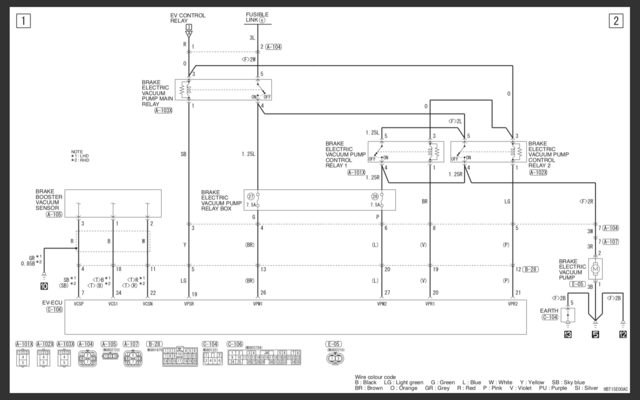
Charrging is controlled by the EV-EVU.
Your test indicates that the EVSE cable is recognized by the EV-ECU, and it is trying to start the charging session by turning on the relay to supply power to the OBC, but it is not receiving a feedback signal that it requires and turns the relay off. It could be a missing signal from the EVSE or from the OBC.

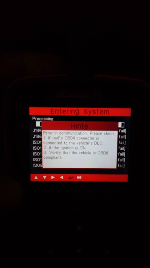
Since your i909 is not detecting 4 of the CAN Buss devices it would seem to point to either a CAN wiring issue or a blown CAN transceiver chip inside the EV-ECU for that CAN channel of the OBC.

i think there is a data item that you could use the i909 to monitor the signal from the EVSE for inserted regular charging and start of regular charging, would have to scroll thru the menu list to find it under the EV-ECU.

Also on the external connector, E-03, pin 7 should have 12V all the time; pin 2 when the relay comes on; and pin 12 is the CHGP line--not sure if it goes high or low to start charging. Maybe you can repeat your test several time to measure the voltage at these pins, e.g. OFF, READY, and EVSE cable plug-in. Might give some clue.

Also would want to ring out the cable between the EV-ECU and the OBC--check for continuity of the CANH and CANL between those boxes, also check that ground pins have continuity to chassis ground.

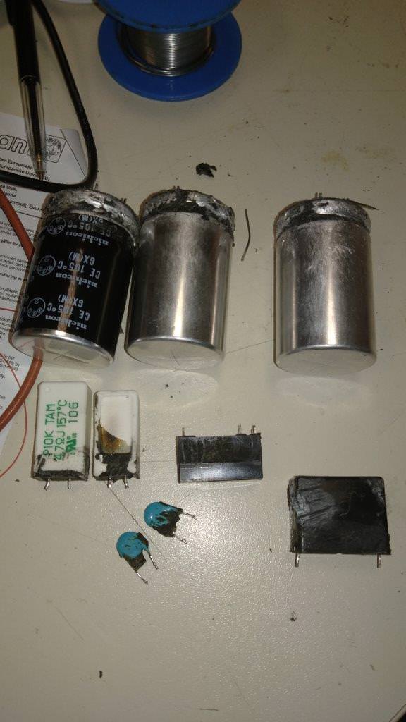
p.s. Just for future reference, it is not necessary to have the exact value for the 3 big capacitors, it would be more important to have the same physical dimensions and pins so that they fit inside the box without the need to modify or hammer out the lid for clearance.
 
There have been three more OBC failures in the last few months. One was from MikeDufty that was mentioned earlier. He took car to dealership, they first swapped out charger, then found that was not the fault, and then finally came back saying there was a wiring fault.

The second OBC Failure was with KT. I pulled the charger from the car and swapped it with one that I had repaired earlier. Once I checked KT's charger, I found the two snubber caps in the doghouse were blown, tested relay and resistors but everything else checked ok. Replaced the blown 20 AMP fuse in the MCU and the snubber caps, put it back in my test IMIEV, and it all works ok.

The Third OBC Failure was sent to a local 3rd party EV repair shop. They purchased a new charger from Mitsubishi, and the owner gave me the broken one. This one had the weird problem of blowing up two of the Uni WA Charging stations, but worked ok on charging at other commercial charging stations. I suspected that since the Uni Charging stations were home made, they were not robust to handle a surge when the charger was first connected. I suspected that the relay that bypassed the resistors in the dog house may have contacts welded closed all the time, so the resistors are bypassed even at first connection. I've pulled this apart, and instead of finding a faulty relay, I find that the 310v 2.2uf X2 Cap in the doghouse is blown. (see attached photo) with this cap blown, The charger was still working well enough to charge from some charging stations, but would actually do some surge damage back to the two charging stations at the Uni.

9h2HHAI.jpg
 
Still waiting for mine, they say they are now waiting for a fuse, due in December some time. Hope to have it back on the road before the end of the year.
They have never said that there wasn't a problem with the charger, just that they found a wiring problem, which may have been an additional issue.
 
MIKEDUFFY: Thanks for clarifying that, sorry I did not mean to add misinfo, so the charger may also been faulty. I remember teilling you about the fuse earlier. I think once they swapped chargers they then came across the fact they also had the blown 20amp fuse in the MCU.
Or they replaced the fuse once, blew ithe fuse again because the OBC was faulty, and now have to wait for another fuse to come in.
There are several people waiting on fuses here in Australia. To get KT's IMIEV back on the road, we used a 20amp 1kv fuse and fuse holder out of a solar power system, added pigtail wires and ring terminals, and connected it across where the original fuse location. This is just temporary until the original fuse with tab ends comes in from Mitsubishi. It's a shame they would not let you have the broken OBC Back. I bet the original fault was the usual snubber caps and 20amp fuse, and the wiring fault was introduced.
 
Back
Top