kiev said:
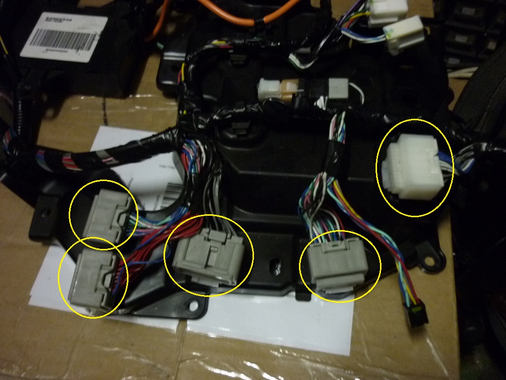
For example all the red wires collected into one; the gray and black wires combined into another;
Ah! The red wires were pointed out to me yesterday, but it didn't register. I'd say that these are essentially shorting bars. These would be the star points for all the commoned wires, such as +12 V (guessing that's the red wires with the faint stripes/bars), 12 V return (black wires, and the gray wires for the shields, commoned at one point to prevent ground loops), and the multi-coloured wires may be paralleling points for the CAN bus. The CAN bus I would think would be better off daisy-chained than star connected, so I may be wrong on that one.
[ tests... ]
Huh. The reds are not all commoned. Each
row is commoned, but the rows don't connect. It looks like the three gray connectors that look the same are all of this type, including two that common different coloured wires. [ Edit: There is one blue wire per row; my guess is that this is +12 V coming in. But why two separate rows? Also, there are 7 and 8 red wires on the two rows, and ten CMUs. I guess +12 V goes to other places as well, such as what I suspect is the insulation leak detector (which I suspect Mitsubishi incorrectly calls a battery detector). ]
With the different looking gray connector that terminates the black and gray wires, the blacks common with each other, but they grays do not. The grays must connect to a black elsewhere. Perhaps on one board; with the disconnected loom as I have it now, the blacks and grays con't connect.
The white connector is a special; it appears to common the thee blues, the three whites, and without checking, I'd say it commons all those gray wires as well. I don't know about the black wires on this connector.
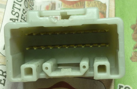
Photos of the row-shorting socket:
[ Edit: imgur.com is back. Embedded images. ]